
Range Rover Classic
82
AIR CONDITIONING
2
DESCRIPTION AND OPERATION
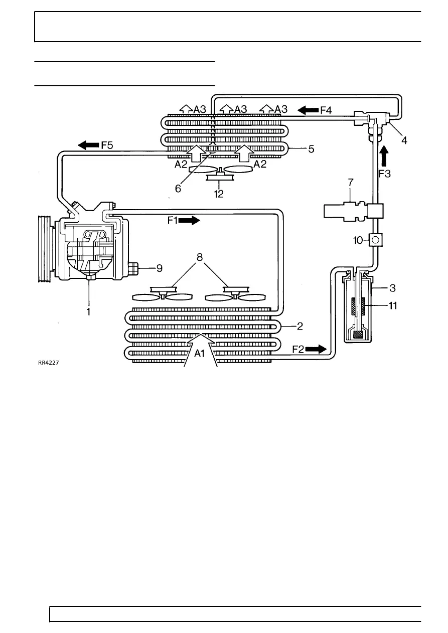
SCHEMATIC LAYOUT OF THE AIR CONDITIONING
SYSTEM
1. Compressor
2. Condenser
3. Receiver/drier
4. Thermostatic expansion valve
5. Evaporator
6. Capillary tube
7. Dual pressure switch
8. Cooling fans to maintain air flow
9. Compressor high pressure relief valve
10. Sight glass - refrigerant
11. Drying agent - receiver/drier
12. Blower motor
A1
Ambient air flow through condenser
A2
Ambient air flow through fan and evaporator
A3
Cooled air flow to vehicle interior
F1
High pressure high temperature refrigerant
vapour
F2
High pressure slightly subcooled refrigerant
liquid
F3
High pressure slightly subcooled refrigerant
liquid with moisture, vapour bubbles and foreign
matter removed
F4
Low pressure low temperature mixed liquid and
vapour
F5
Low pressure slightly superheated refrigerant
vapour