
Navigator 4WD V8-5.4L (2010)
8. WARNING: Check the seat side air bag deployment chute for damage. The deployment chute must not be repaired. If there is any
damage to the deployment chute, a new seat back trim cover and deployment chute must be installed as a unit. Failure to follow these
instructions may result in the seat side air bag module deploying incorrectly and increase the risk of serious personal injury or death in a
crash.
WARNING: Before installing the seat side air bag module/deployment chute assembly:
-
Inspect the side air bag module and mounting surfaces for any damage or foreign material.
-
Remove any foreign material from the mounting surfaces of the deployment chute, the seat backrest frame mounting bracket and the
air bag module cavity in the seat backrest foam pad.
-
Install new parts if damaged.
Failure to follow these instructions may result in the seat side air bag deploying incorrectly, which increases the risk of serious personal injury
or death in a crash.
WARNING: If the seat side air bag cover has been damaged or separated from its mounting, or if the air bag material has been exposed,
install a new seat side air bag module. Never try to repair the seat side air bag module. Failure to follow these instructions may result in
the seat side air bag deploying incorrectly, which increases the risk of serious personal injury or death in a crash.
To install, reverse the removal procedure.
Seat Cushion Cover - Front
Seat Cushion Cover - Front
Removal and Installation
All seats
WARNING: Never probe the electrical connectors on safety belt buckle/retractor pretensioners or adaptive load limiting retractors. Failure to
follow this instruction may result in the accidental deployment of the safety belt pretensioners or adaptive load limiting retractors, which
increases the risk of serious personal injury or death.
NOTE: The air bag warning indicator illuminates when the correct Restraints Control Module (RCM) fuse is removed and the ignition switch is ON.
NOTE: The Supplemental Restraint System (SRS) must be fully operational and free of faults before releasing the vehicle to the customer.
NOTE: For additional component identification and locations, refer to Seat - Exploded View, Front See: Service and Repair/Front Seat/Seat -
Exploded View, Front.
NOTE: For correct installation, note wire harness routing.
1. Remove the seat. For additional information, refer to Seat - Front See: Service and Repair/Front Seat/Seat - Front.
2. If equipped, pull and remove the manual lumbar knob.
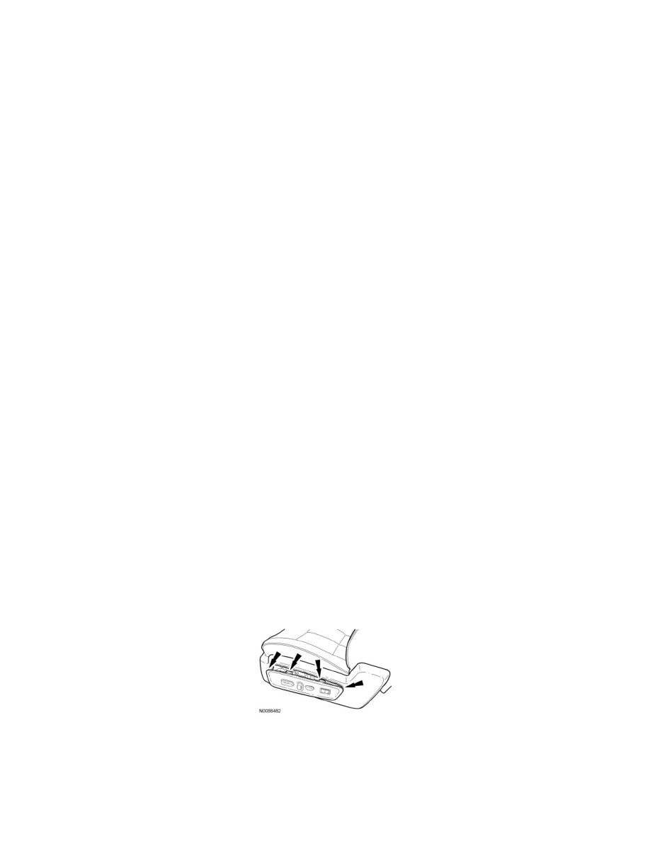
Side shield with insert
3. Release the retainers and remove the insert from the side shield.
-
For power seat, disconnect the electrical connector(s).
4. Remove the front side shield screw.