
Navigator 4WD V8-5.4L (2010)
-
Is the voltage greater than 10 volts?
Yes
GO to T2.
No
VERIFY the Smart Junction Box (SJB) fuse 3 (15A) is OK. If OK, REPAIR the circuit in question. If not OK, REFER to the Wiring Diagrams to
identify the possible causes of the circuit short. CLEAR the DTCs. REPEAT the network test with the scan tool. See: Diagrams/Electrical
Diagrams/Diagrams By Number
-------------------------------------------------
T2 CHECK THE APIM GROUND CIRCUITS FOR AN OPEN
-
Ignition OFF.
-
Disconnect: Negative Battery Cable.
-
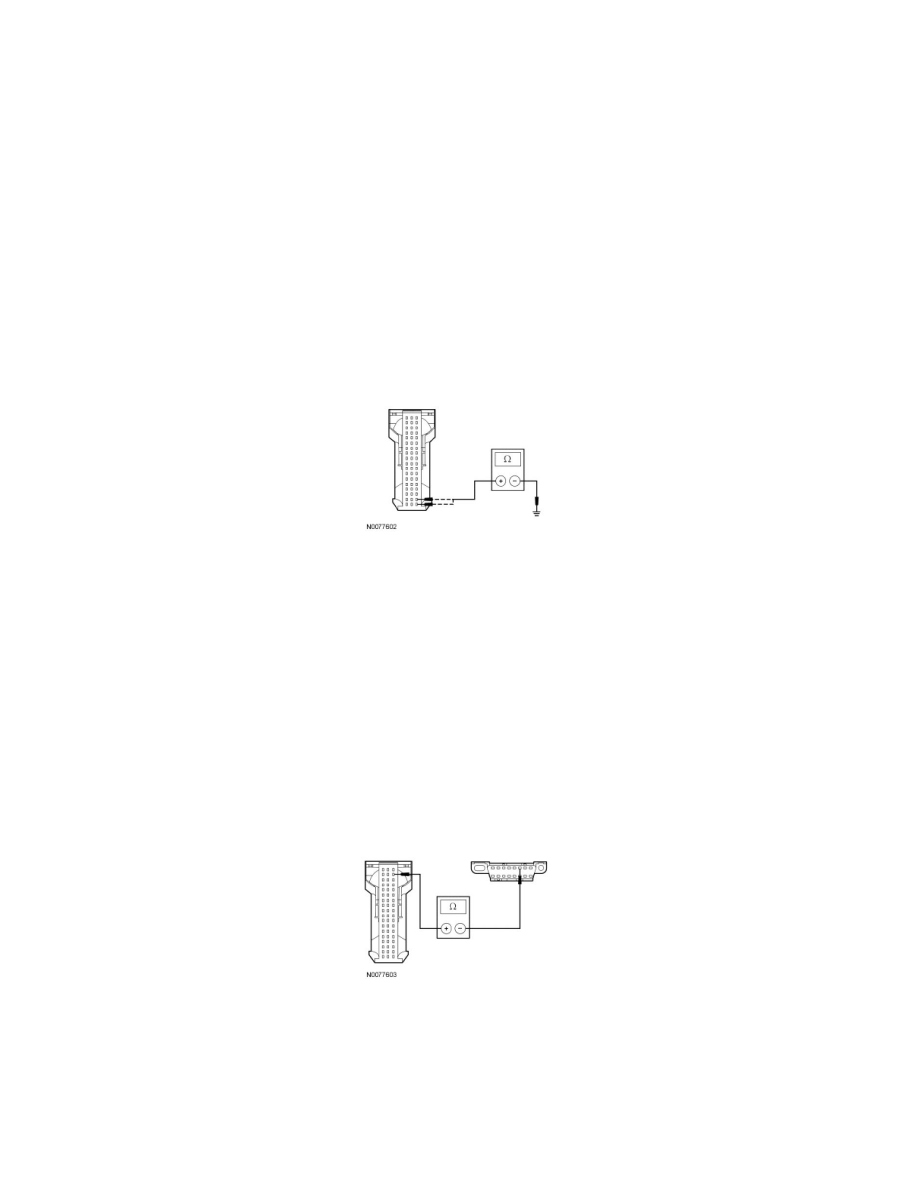
Measure the resistance between the APIM C3342-37, circuit GD114 (BK/BU), harness side and ground; and between the APIM C3342-38, circuit
GD114 (BK/BU), harness side and ground.
-
Are the resistances less than 5 ohms?
Yes
GO to T3.
No
REPAIR the circuit in question. CONNECT the negative battery cable. CLEAR the DTCs. REPEAT the network test with the scan tool.
-------------------------------------------------
T3 CHECK THE HS-CAN CIRCUITS BETWEEN THE APIM AND THE DLC FOR AN OPEN
-
Measure the resistance between the APIM C3342-53, circuit VDB04 (WH/BU), harness side and the DLC C251-6, circuit VDB04 (WH/BU),
harness side.
-
Measure the resistance between the APIM C3342-54, circuit VDB05 (WH), harness side and the DLC C251-14, circuit VDB05 (WH), harness
side.