
Navigator 4WD V8-5.4L SOHC VIN L (1998)
6. Rotate the differential pinion gears to align the differential pinion shaft bore.
7. Insert the differential pinion shaft, and install a new differential pinion shaft lock bolt finger-tight.
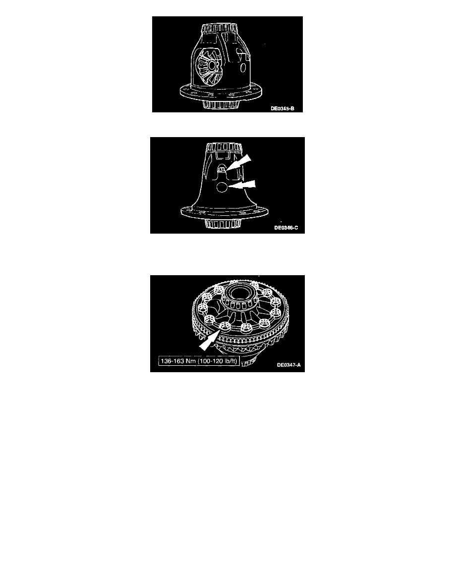
8. Press the new anti-lock speed sensor ring and the ring gear on the differential case.
-
The notch on the differential case flange and the notch on the anti-lock speed sensor ring must be aligned.
9. Install the ring gear bolts and tighten.
-
Apply Stud and Bearing Mount EOAZ-19554-BA or equivalent meeting Ford specification WSK-M2G349-A1 to the ring gear bolts.
10. Install the differential case.
Traction-Lok - Differential Case and Rear Gear