
Navigator 4WD V8-5.4L VIN 5 (2006)
6. Connect the CHT sensor jumper harness electrical connector.
7. Connect the LH and RH KS electrical connectors.
8. Connect the manifold vacuum tube to the support bracket and the valve cover stud.
9. Connect the brake booster vacuum hose to the intake manifold vacuum tube.
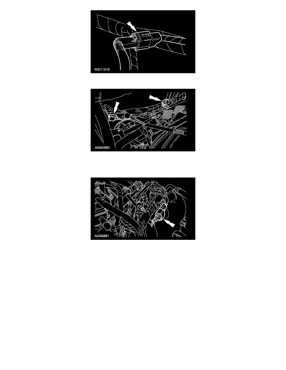
10. Connect the heated PCV intake fitting electrical connector.
11. Connect the TP sensor and electronic acceleration control electrical connectors.
12. Connect the 8 fuel injector electrical connectors.
13. Connect the fuel rail pressure and temperature sensor electrical connector and vacuum connector.
14. Connect the fuel supply spring lock coupling to the fuel rail. For additional information, refer to Fuel Delivery and Air Induction.
15. Position the PCV tube and connect the quick connect couplings. For additional information, refer to Fuel Delivery and Air Induction.
16. Position the EVAP tube and connect the quick connect coupling to the intake manifold. For additional information, refer to Fuel Delivery and Air
Induction.
17. Connect the heater coolant hose to the coolant bypass.
18. Connect the upper radiator hose to the thermostat housing.
19. Install the generator. For additional information, refer to Alternator.
20. Install the air cleaner. For additional information, refer to Fuel Delivery and Air Induction.
21. Fill and bleed the engine cooling system. For additional information, refer to Cooling System.