
Navigator 4WD V8-5.4L VIN 5 (2006)
Removal and Installation
WARNING: The electrical power to the air suspension system must be shut off prior to hoisting, jacking or towing an air suspension vehicle.
This can be accomplished by turning off the air suspension switch located in the LH rear quarter trim panel.
Failure to do so can result in unexpected inflation or deflation of the air springs, which can result in shifting of the vehicle during these
operations. Failure to follow these instructions may result in personal injury.
CAUTION: Suspension fasteners are critical parts because they affect performance of vital parts and systems and their failure can result in major
service expense. A new part with the same part number must be installed if installation becomes necessary. Do not use a replacement part of lesser
quality or substitute design. Torque values must be used as specified during reassembly to make sure of correct retention of these parts.
1. If equipped, turn the air suspension switch to the OFF position.
2. With the vehicle in NEUTRAL, position it on a hoist.
3. NOTE: Use the hex holding feature to prevent the stud from turning while removing the nut.
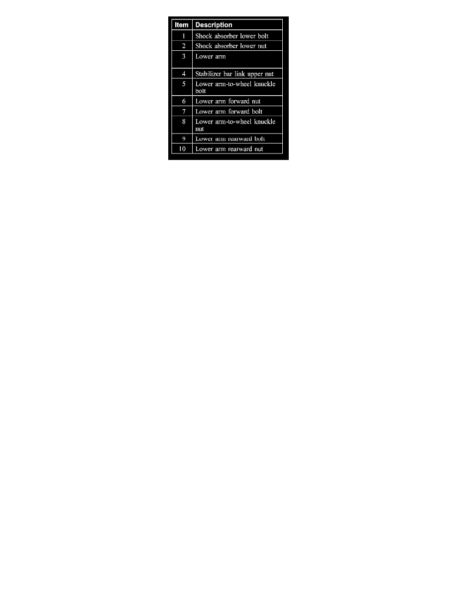
Remove and discard the stabilizer bar link upper nut.
^
To install, tighten to 80 Nm (59 ft. lbs.).
4. Remove the shock absorber lower bolt and nut.
^
Discard the nut.
^
To install, tighten to 400 Nm (295 ft. lbs.).
5. Remove the lower arm forward nut and bolt.
^
Discard the nut.
^
To install, tighten to 250 Nm (184 ft. lbs.).
6. Remove the lower arm rear-ward nut and bolt.
^
Discard the nut.
^
To install, tighten to 250 Nm (184 ft. lbs.).
7. Remove the lower arm-to-wheel knuckle bolt, nut and the lower arm.
^
Discard the nut.
^
To install, tighten to 400 Nm (295 ft. lbs.).
8. If necessary, using a suitable press and adapters, remove the lower arm-to-wheel knuckle bushing.
9. CAUTION: Do not tighten the lower arm forward and rearward nuts and bolts until the installation procedure is complete and the weight of the
vehicle is resting on the wheel and tire assemblies.
To install, reverse the removal procedure.
10. Check and, if necessary, adjust the rear alignment.