
Town Car V8-4.6L VIN V Flex Fuel (2006)
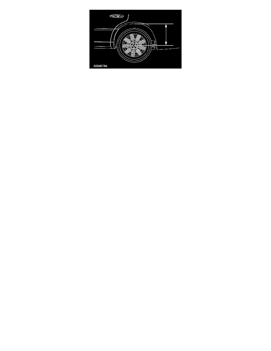
2. For reference during the installation procedure, measure the distance from the lip of the fender to the center of the wheel hub with the vehicle in a
static level ground position.
3. With the vehicle in NEUTRAL, position it on a hoist.
4. CAUTION: Do not use excessive force when removing the pivot bolt and flag nut on the right upper suspension arm-to-axle bracket. Damage to
the brake line can occur.
Remove the upper arm to axle bolt and flag nut.
^
Discard the flag nut and bolt.
^
To install, tighten to 90 Nm (66 ft. lbs.).
5. Remove the upper arm to frame bolt and the upper arm.
^
Discard the nut and bolt.
^
To install, tighten to 150 Nm (111 ft. lbs.).
6. NOTE: The rear suspension upper arms are interchangeable from side-to-side with "FRONT" and "OUTBOARD" stamped on the side of the
arms for positioning during installation.
NOTE: Before tightening the fasteners, use a suitable Jack or Jack stands to raise the suspension until the distance between the lip of the fender
and the center of the wheel hub is equal to the measurement taken in the removal procedure.
To install, reverse the removal procedure.
Lower Arm
Lower Arm