
Capri L4-140 2.3L SOHC Turbo (1983)
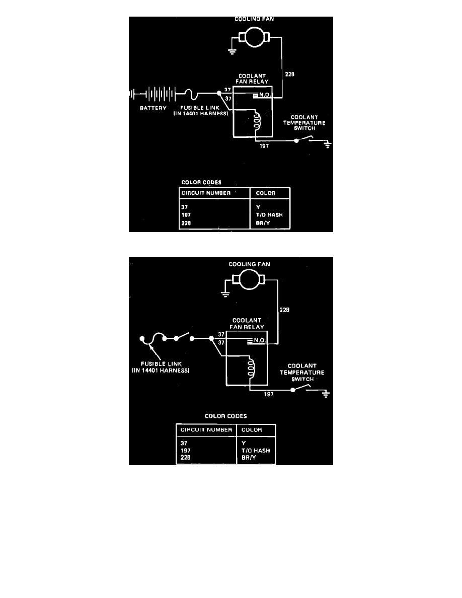
Fig. 2 Electric engine cooling fan wiring diagram. Type 1
Fig. 3 Electric engine cooling fan wiring diagram. Type 2
Refer to Figs. 2 and 3, during the following procedures.
1.
Check cooling fan fusible link. If fusible link is not blown, go to step 2. If blown, repair and retest.
2.
Disconnect fan motor electrical connector, then connect a jumper wire from motor ground connection to a known good ground and a jumper wire
from battery positive to motor B+ connection. If motor does not run, replace motor. If motor runs, reconnect electrical connector and proceed to
step 3.
3.
On type 2 systems, turn ignition ``On.'' On both systems disconnect coolant temperature switch connector, then connect a jumper wire from
connector to ground. If motor runs, check switch ground. If ground is satisfactory, replace coolant temperature switch. If motor does not run,
proceed to step 4.
4.
Using an ohmmeter, check continuity of wire 197 from temperature switch to fan relay. If no continuity exists, check circuit 197 for opens. If
continuity exists, connect a jumper wire from coolant temperature switch connector to ground and proceed to step 5.