
Cougar/XR7 L4-140 2.3L SOHC Turbo (1983)
5.
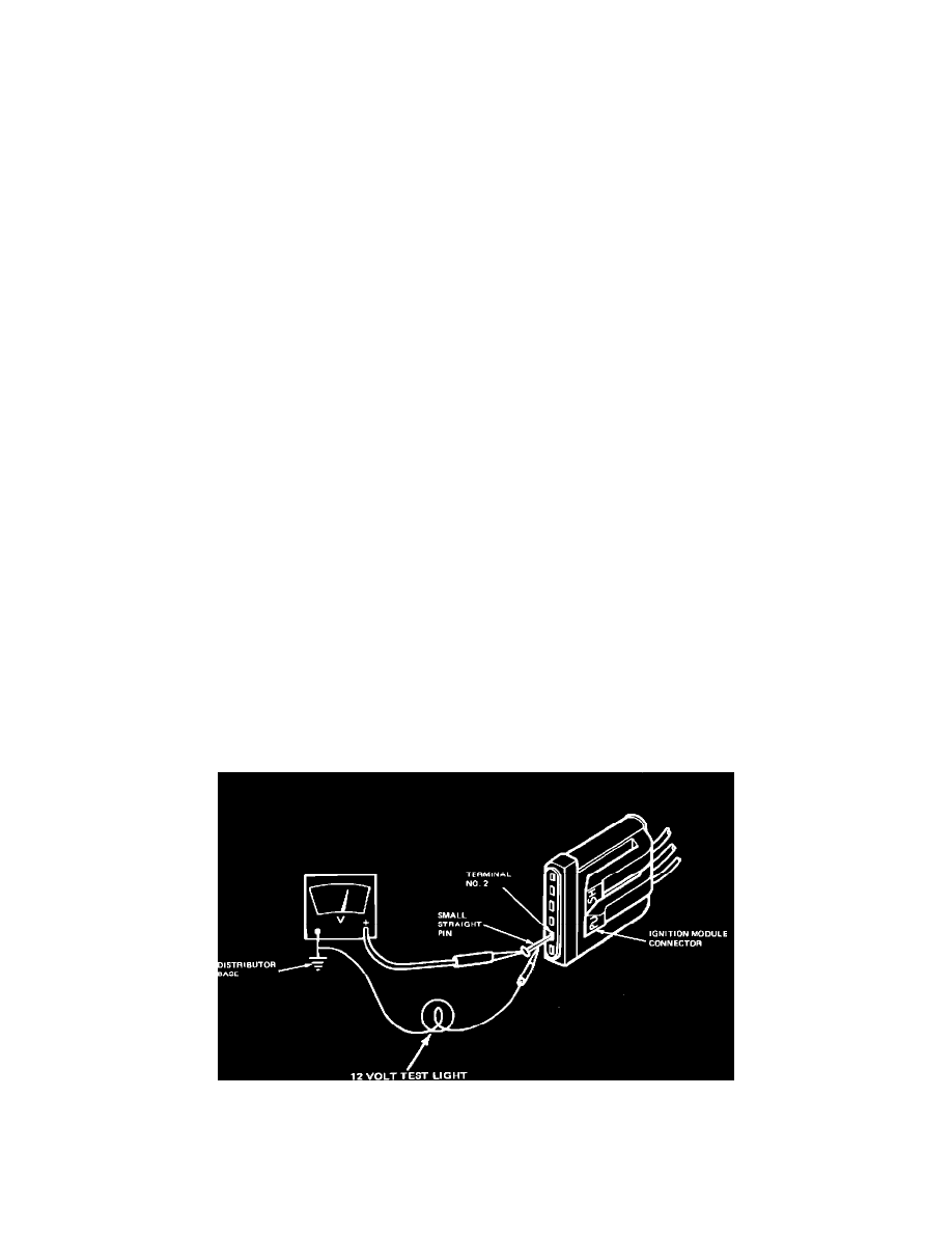
Following table below, measure connector terminal voltage by attaching VOM to small straight pin inserted into connector terminal and turning
ignition switch to position shown.
CAUTION: Do not allow straight pin to contact electrical ground.
CONNECTOR
IGNITION SWITCH
TERMINAL
WIRE/CIRCUIT
TEST POSITION
#2
TO IGNITION
RUN
COIL (-) TERMINAL
#3
RUN CIRCUIT
RUN AND START
#4
START CIRCUIT
START
6.
Turn ignition switch to Off position.
7.
Remove straight pin.
8.
Reconnect wire to S terminal of starter relay.
TEST RESULT
TEST RESOLUTION
90 percent of
^ Test result OK.
battery
^ Go to Part 2, Test 6.
voltage minimum
Less than 90
^ Inspect for faults in wiring
percent of
harness and connectors.
battery
^ Refer to vehicle wiring
voltage
diagram for appropriate
circuit.
^
Damaged or worn ignition switch, Refer to Shop Manual, Group 33.
Primary Circuit Continuity
TFI-IV
Part 2
Test 8
TEST EQUIPMENT: VOM, STRAIGHT PIN
TEST PROCEDURE
1.
Separate wiring harness connector from ignition module. Inspect for dirt, corrosion, and damage.
NOTE:
PUSH connector tabs to separate.