
Cougar/XR7 V8-4.6L VIN W (1997)
Hydraulic Control Assembly - Antilock Brakes: Service and Repair
(Part 1 Of 2)
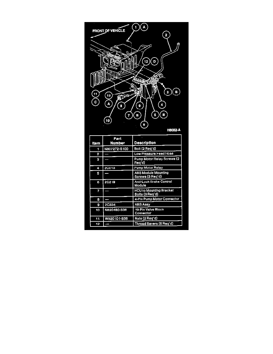
REMOVAL
1. Remove battery.
2. Remove power distribution box-to-battery tray retaining bolt.
3. Remove battery tray.
4. Disconnect 16-pin valve body to wire harness connector.
5. Raise and support vehicle and remove LH front tire and wheel assembly.
6. Remove LH inner fender splash shield.
7. Disconnect 3-pin fluid level switch connector, 4-pin pump motor connector, 4-pin pump motor relay connector and 55-pin ABS control module
connector.
CAUTION: The brake master cylinder will drain if the feed hose is not pinched off. DO NOT allow brake fluid to come in contact with wiring or
paint. Immediately rinse any paint or wiring with water if brake fluid comes in contact with them.
8. Remove low pressure feed hose from hydraulic control unit reservoir. Clamp or plug hose.
9. Disconnect LH front brake tube from hose at the hose mounting bracket.
10. Remove the two lower hydraulic control unit assembly mounting bracket attaching screws.
11. Lower vehicle and disconnect the five brake tube connections at the junction block. Remove the two junction block retaining nuts.
CAUTION: Do not allow the two upper bushings to turn in the bracket while loosening the two upper mounting bolts. Hold the bushings with a