
Grand Marquis V8-302 5.0L VIN F TBI (1984)
Evaporator Case: Service and Repair
With Automatic Temperature Control
REMOVAL
1. Disconnect the ground cable from the battery.
2. Discharge the refrigerant from the air conditioning system into an approved recovery unit. Observe all safety precautions.
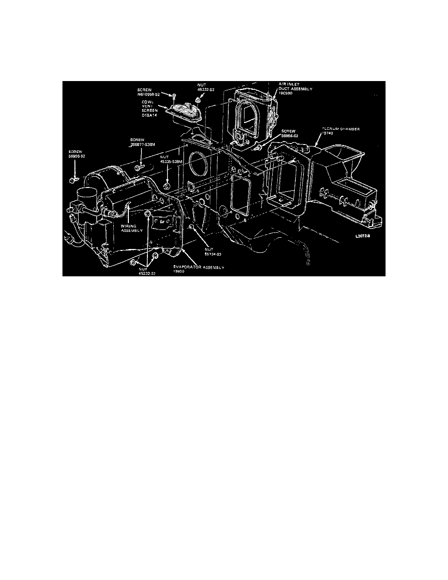
Evaporator Case/Plenum Removal
3. Disconnect the suction hose from the suction accumulator/drier. Plug the openings to the suction accumulator/drier and suction hose and position
the hose away from the evaporator assembly.
4. Unplug the two-wire connector from the clutch cycling pressure switch on the suction accumulator/drier.
5. Disconnect the liquid line from the evaporator inlet tube. Plug openings to the liquid line and evaporator inlet tube and position the liquid line
away from the evaporator assembly.
6. Drain the radiator coolant into a clean container. Save the coolant for refilling the cooling system.
7. Loosen the heater hose clamps and disconnect the heater hoses from the inlet and outlet heater core tubes.
8. From the passenger compartment, turn the steering wheel to the left to position the right front wheel so that the wheel well splash panel support
bracket is accessible.
9. Remove the screw and splash panel support bracket from the back portion of the wheel well. This will allow the splash panel to be depressed
slightly for extra clearance when removing and replacing the evaporator assembly.
10. Remove the six screws holding the right side of the hood seal bracket assembly. Remove the copper hood ground clip from underneath the hood
seal and remove the hood seal bracket assembly to the right side of the vehicle.
11. Loosen the retaining clamp and disconnect the emission hose that passes over the top of the evaporator case assembly. Position the emission hose
and all vacuum hoses and movable wires away from the evaporator case assembly.
12. Disconnect the blower motor ground wire from the body frame and position away from the evaporator assembly.
13. Disconnect the blower motor wiring connector from the wiring harness hard shell connector.
14. Disconnect the two large wire harnesses (which cross the evaporator assembly) at the various connecting points and position them away from the
evaporator assembly.
15. From the passenger side of the dash panel, fold back the carpeting, if necessary, on the right side of floor. Remove the bottom left screw of the two
screws that support the inlet recirculation air duct assembly.
16. From the passenger compartment, disconnect the ambient sensor air tube from the evaporator sensor air tube port.
17. From the engine side of the dash panel, remove three nuts (one upper and two lower) from the three evaporator assembly mounting studs. Also
remove two screws (one drill-point and one sheet metal) from the blower motor and wheel portion of the case assembly.
18. Pull the bottom of the evaporator case assembly away from the dash panel to disengage the evaporator ambient sensor air tube port and the two
bottom studs. Move the top of the evaporator assembly away from the dash panel, disengaging it from the top stud, and maneuver the case up and
over the wheel well splash panel. The splash panel may be pushed downward slightly for additional clearance.
INSTALLATION
1. Position the evaporator assembly near to the dash panel by maneuvering it down past the wheel splash panel. If necessary, push the splash panel
downward slightly for extra clearance.