
LN7 L4-098 1.6L VIN 4 2-bbl (1982)
Steering Gear: Service and Repair
Input Shaft & Valve Assembly
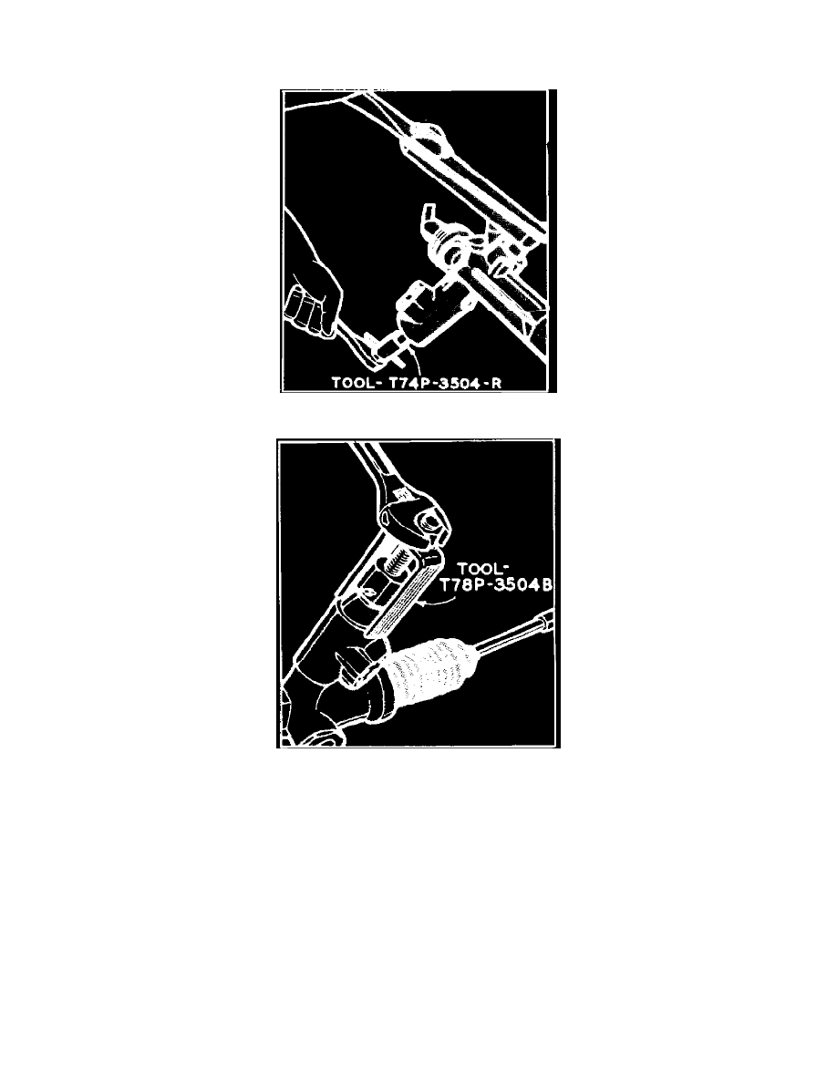
Fig. 5 Removing pinion bearing locknut
Fig. 6 Removing input shaft & control valve assembly from housing
Disassembly
1.
Thoroughly clean steering gear housing, then mount gear in holding fixture T57L-500-B or equivalent.
2.
Do not remove the external pressure lines unless damaged or leaking. Loosen yoke plug locknut and yoke plug to relieve preload on rack.
3.
Remove pinion bearing plug, then use tool No. T74P-3504-R, or equivalent, (T86P-3504-K Sable & Taurus) to hold input shaft in position and
remove pinion bearing locknut with a {11-16} in. socket, Fig. 5. Discard pinion bearing locknut and use a new nut at assembly.
4.
Using a suitable tool, pry input shaft dust seal out of valve housing. Use care not to damage valve housing.
5.
Remove snap ring from valve housing.
6.
Attach puller T78P-3504-B, or equivalent, to input shaft and remove input shaft seal and bearing and valve body, Fig. 6.. On Sable & Taurus,
attach valve body puller (bridge) T86P-3504-B and valve body puller (screw) T78P-3504-B and remove input shaft seal, input shaft and and valve
body.
7.
Use tool No. T78P-3504-E, or equivalent, and a suitable slide hammer to remove lower pinion shaft seal.
8.
Remove pinion bearing from gear housing using tool No. T58L-101-A, or equivalent, and a suitable slide hammer.
9.
If necessary, remove O-rings from input shaft and valve assembly. Remove O-rings by pushing rings to one side and inserting a small pointed
knife to cut ring off.
Assemble