
Mariner 2WD L4-2.5L (2009)
The system is operating correctly at this time. The concern may have been caused by a loose or corroded connector. CLEAR the DTCs. REPEAT the
network test with the scan tool.
-------------------------------------------------
Pinpoint Test L: The HVAC Module Does Not Respond To The Scan Tool
Communications Network
Pinpoint Tests
Pinpoint Test L: The HVAC Module Does Not Respond To The Scan Tool
Refer to Wiring Diagram Set 14 (Escape/Mariner, Escape Hybrid/Mariner Hybrid), Module Communications Network for schematic and connector
information. See: Diagrams/Electrical Diagrams/Diagrams By Number
Refer to Wiring Diagram Set 55 (Escape/Mariner, Escape Hybrid/Mariner Hybrid), Automatic Climate Control System for schematic and connector
information. See: Diagrams/Electrical Diagrams/Diagrams By Number
Normal Operation
The HVAC module communicates with the scan tool through the Medium Speed Controller Area Network (MS-CAN). Circuits VDB06 (GY/OG)
(MS-CAN +) and VDB07 (VT/OG) (MS-CAN -) provide the network connection to the HVAC module. Voltage to the HVAC module is provided by
circuit SBP15 (WH/RD) and circuit CBP37 (WH). Ground is provided by circuit GD114 (BK/BU).
NOTE: The Electronic Manual Temperature Control (EMTC) HVAC module does not communicate with the scan tool.
This pinpoint test is intended to diagnose the following:
-
Fuse
-
Wiring, terminals or connectors
-
HVAC module
PINPOINT TEST L: THE HVAC MODULE DOES NOT RESPOND TO THE SCAN TOOL
NOTICE: Use the correct probe adapter(s) when making measurements. Failure to use the correct probe adapter(s) may damage the
connector.
NOTE: Failure to disconnect the battery when instructed will result in false resistance readings. Refer to Battery.
-------------------------------------------------
L1 CHECK THE HVAC MODULE VOLTAGE SUPPLY CIRCUIT FOR AN OPEN
-
Ignition OFF.
-
Disconnect: HVAC Module C2356a (DATC) or C2357a (EMTC).
-
Ignition ON.
-
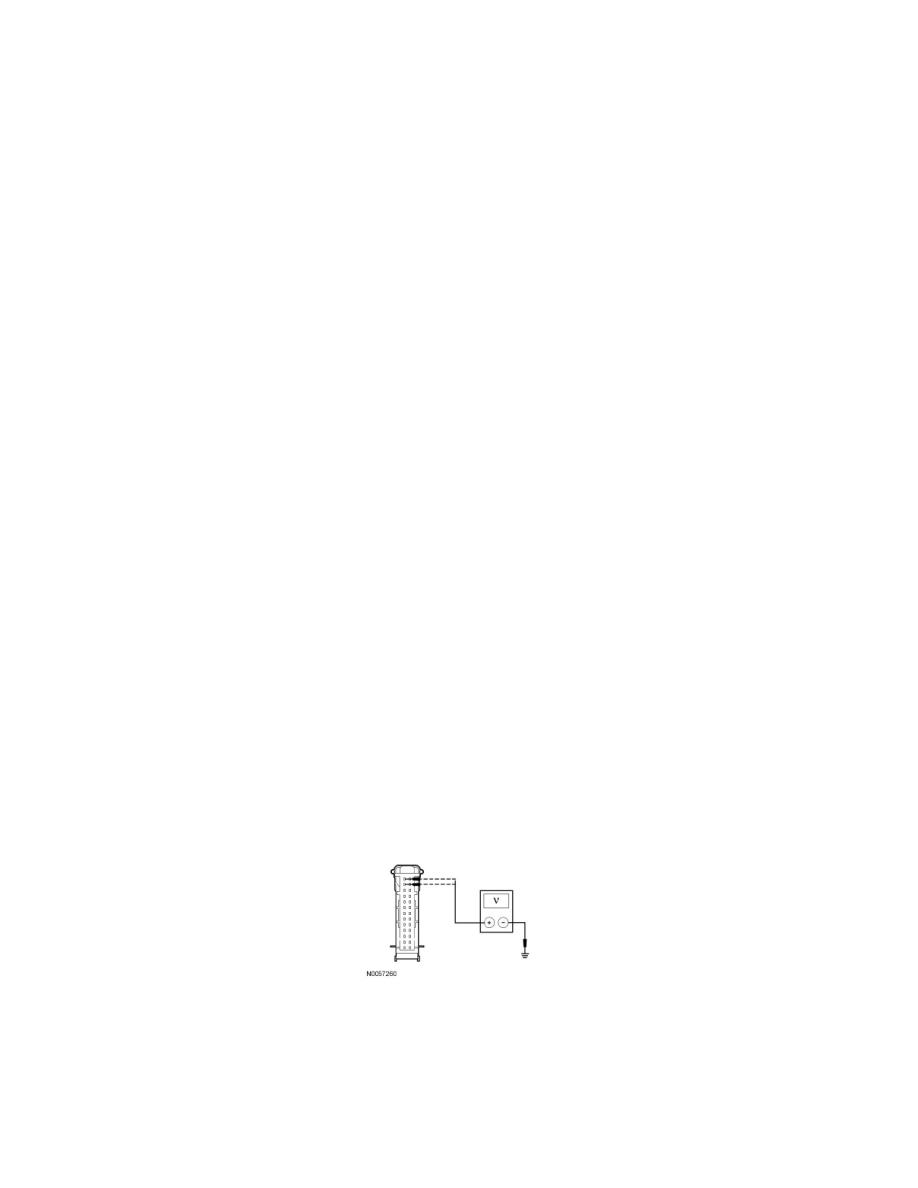
Measure the voltage between the HVAC module C2356a-12 or C2357a-12, circuit CBP37 (WH), harness side and ground and between the HVAC
module C2356a-13 or C2357a-13, circuit SBP15 (WH/RD) harness side and ground.
-
Are the voltages greater than 10 volts?
Yes
GO to L2.
No
VERIFY the Smart Junction Box (SJB) fuse 15 (10A) or fuse 37 (10A) is OK. If OK, REPAIR the circuit in question. If not OK, REFER to the Wiring