Mariner 2WD V6-3.0L (2008)

Part 2
Disassembly
WARNING:
-
Always carry or place a live air bag module with the air bag and deployment door/trim cover/tear seam pointed away from the body. Do
not set a live air bag module down with the deployment door/trim cover/tear seam face down. Failure to follow these instructions may
result in serious personal injury in the event of an accidental deployment.
-
Never probe the electrical connectors on safety belt buckle/retractor pretensioners or adaptive load limiting retractors. Failure to follow
this instruction may result in the accidental deployment of the safety belt pretensioners or adaptive load limiting retractors, which
increases the risk of serious personal injury or death.
-
If the seat side air bag cover has been damaged or separated from its mounting, or if the air bag material has been exposed, install a new
seat side air bag module. Never try to repair the seat side air bag module. Failure to follow these instructions may result in the seat side
air bag deploying incorrectly, which increases the risk of serious personal injury or death in a crash.
-
Front seat backrest trim covers installed on seats equipped with seat side air bags cannot be repaired. A new trim cover must be installed.
Cleaning is permissible. Failure to follow these instructions may result in the seat side air bag module deploying incorrectly and increase
the risk of serious personal injury or death in a crash.
NOTE:
-
If a side air bag deployment took place, a new seat back pad, trim cover and side air bag module and nuts must be installed. The seat back frame
should be replaced if necessary.
-
The air bag warning indicator illuminates when the restraints control module (RCM) fuse is removed and the ignition switch is ON. This is normal
operation and does not indicate a supplemental restraint system (SRS) fault.
-
The SRS must be fully operational and free of faults before releasing the vehicle to the customer.
-
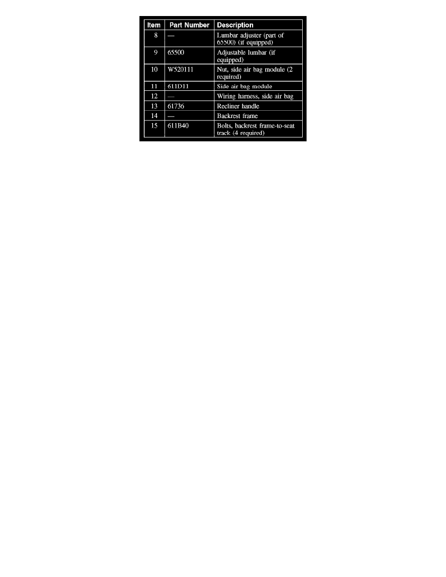
Driver seat shown, passenger similar.
All seats
1. Remove the front seat.
2. Remove the seat backrest.
3. Remove the head restraint.
-
Release the 2 guide locks.
4. Pull outward and remove the 2 head restraint guides.
Seats with lumbar adjust
5. Remove the lumbar knob.
All seats
6. Release the backrest trim cover J-clip.
