
Mariner 2WD V6-3.0L VIN 1 (2006)
Brake Lamp: Initial Inspection and Diagnostic Overview
Principles of Operation
PRINCIPLES OF OPERATION
The smart junction box (SJB) monitors the input from the stoplamp switch. When the brake pedal is applied, voltage is routed to the SJB and the high
mounted stoplamp. The SJB then supplies voltage to the rear stoplamps.
The SJB utilizes a protective circuit strategy for many of its outputs (for example, the headlamp output circuit). Output loads (current level) are
monitored for excessive current (typically short circuits) and are shut down (turns off the voltage or ground provided by the module) when a fault is
detected. A continuous diagnostic trouble code (DTC) is stored at that time for the fault. The circuit will then reset after an ignition cycle or customer
demand of the function (switching the component on, 30-minute battery saver being energized). When an excessive circuit load occurs several times, the
module shuts down the output until a service procedure is performed. At the same time, the continuous DTC that was stored on the first failure will not
clear by a command to clear the continuous DTCs. The module will not allow this code to be cleared or the circuit restored to normal until a successful
on-demand self-test proves that the fault has been repaired. After the on-demand self-test has successfully completed (no on-demand DTCs present), the
continuous DTC will have been cleared and the circuit function will return.
Inspection and Verification
INSPECTION AND VERIFICATION
1. Verify the customer concern.
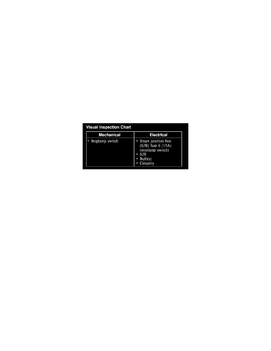
Visual Inspection Chart
2. Visually inspect for obvious signs of mechanical or electrical damage.
3. If an obvious cause for an observed or reported concern is found, correct the cause (if possible) before proceeding to the next step.
NOTE:
-
Make sure the multifunction switch is in the OFF position.
-
Make sure the multifunction switch is in the LOW BEAM position.
4. If the cause is not visually evident, connect the diagnostic tool to the data link connector (DLC) and select the vehicle to be tested from the
diagnostic tool menu. If the diagnostic tool does not communicate with the vehicle:
-
Check that the program card is correctly installed.
-
Check the connections to the vehicle.
-
Check the ignition switch position.
5. If the diagnostic tool still does not communicate with the vehicle, refer to the diagnostic tool operating manual.
6. Carry out the diagnostic tool data link test. If the diagnostic tool responds with:
-
CAN or ISO circuit fault; all electronic control units no response/not equipped, refer to Information Bus (Module Communications Network).
-
No response/not equipped for SJB, refer to Body Control Systems (Multifunction Electronic Control Module).
-
System passed, retrieve and record the continuous diagnostic trouble codes (DTCs), erase the continuous DTCs and carry out self-test
diagnostics for the SJB.
7. If the DTCs retrieved are related to the concern, go to the Smart Junction Box (SJB) Diagnostic Trouble Code (DTC) Index. See: Diagnostic
Trouble Code Descriptions
8. If no DTCs related to the concern are retrieved, GO to Symptom Chart. See: Symptom Related Diagnostic Procedures