
Mariner 4WD L4-2.5L (2010)
NOTE: Failure to disconnect the battery when instructed will result in false resistance readings. Refer to Battery.
-------------------------------------------------
L1 CHECK THE HVAC MODULE VOLTAGE SUPPLY CIRCUIT FOR AN OPEN
-
Ignition OFF.
-
Disconnect: HVAC Module C2356a (DATC) or C2357a (EMTC) .
-
Ignition ON.
-
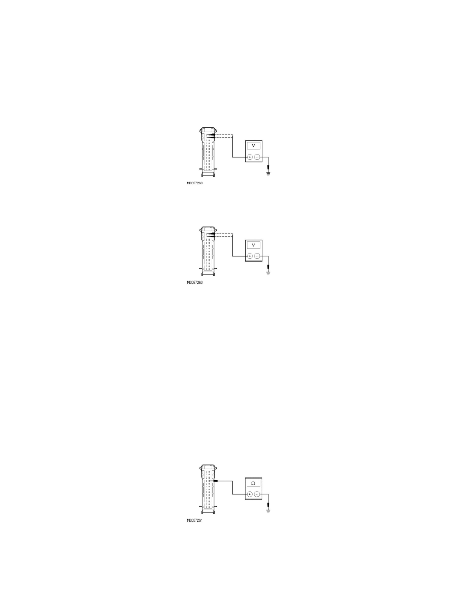
For gasoline engines (without hybrid), measure the voltage between the HVAC module C2356a-12 or C2357a-12, circuit CBP37 (WH), harness
side and ground; and between the HVAC module C2356a-13 or C2357a-13, circuit SBP15 (WH/RD), harness side and ground.
-
For hybrid, measure the voltage between the HVAC module C2356a-12 circuit CH122 (WH/OG), harness side and ground; and between the
HVAC module C2356a-13, circuit SBP15 (WH/RD), harness side and ground.
-
Are the voltages greater than 10 volts?
Yes
GO to L2.
No
VERIFY the Smart Junction Box (SJB) fuse 15 (10A) or fuse 37 (10A) is OK. If OK, REPAIR the circuit in question. If not OK, Refer to the Wiring
Diagrams to identify the possible causes of the circuit short. CLEAR the DTCs. REPEAT the network test with the scan tool. See: Diagrams/Electrical
Diagrams/Diagrams By Number
-------------------------------------------------
L2 CHECK THE HVAC MODULE GROUND CIRCUIT FOR AN OPEN
-
Ignition OFF.
-
Disconnect: Negative Battery Cable .
-
Measure the resistance between the HVAC module C2356a-23 or C2357a-23, circuit GD114 (BK/BU), harness side and ground.
-
Is the resistance less than 5 ohms?
Yes
GO to L3.