
Merkur Scorpio V6-179 2.9L (1989)
Camshaft: Service and Repair
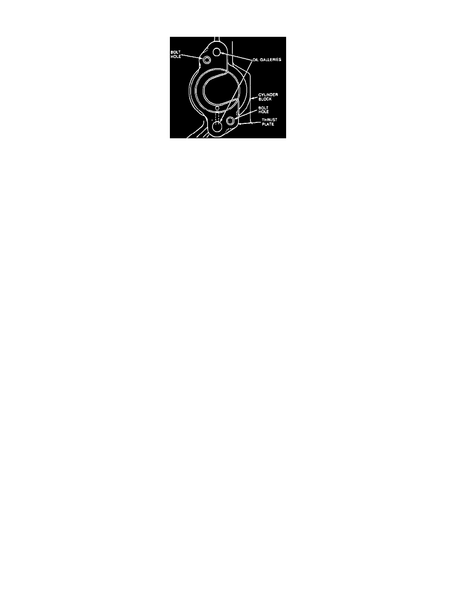
Fig. 9 Camshaft Thrust Plate Installation
1.
Disconnect battery ground cable.
2.
Remove upper fan shroud attaching bolts and rivets and the shroud. Retain rivets and radiator insulators for use during installation.
3.
Remove engine driven cooling fan. Viscous clutch nut has left hand threads which must be rotated clockwise for removal.
4.
Drain cooling system, then disconnect upper and lower hoses from radiator.
5.
On models equipped with automatic transmission, disconnect and plug transmission oil cooler lines from radiator.
6.
On all models, disconnect A/C cooling fan switch electrical connector.
7.
Raise and support vehicle.
8.
Remove lower mount attaching bolts, then depress tabs to disengage upper studs.
9.
Lower radiator assembly from vehicle.
10.
Loosen A/C condenser retaining bolts.
11.
Remove upper and lower engine mount retaining nuts, then lower vehicle.
12.
Remove grille attaching screws and the grille.
13.
Remove A/C condenser attaching bolts, then lower condenser and cooling fan from vehicle.
14.
Remove cylinder head as previously described.
15.
Remove valve lifters using a magnet. Note installed positions of lifters for installation reference.
16.
Remove engine front cover as previously described.
17.
Remove all drive belts, then the water pump as described under WATER PUMP.
18.
Remove timing chain and sprockets as previously described.
19.
Raise and support engine and transmission assembly to provide adequate clearance for camshaft removal.
20.
Remove camshaft thrust plate and attaching bolts, then carefully slide camshaft from engine.
21.
Reverse procedure to install, noting the following:
a. Lubricate camshaft journals and cam lobes with heavy engine oil prior to installation.
b. Install spacer ring with chamfered side toward camshaft, then install camshaft key.
c. Install thrust plate to cover main oil gallery, Fig. 9, and torque attaching bolts to specification.
d. Torque upper and lower engine mount retaining nuts to specifications.