
Merkur Scorpio V6-179 2.9L (1989)
Intake Manifold: Service and Repair
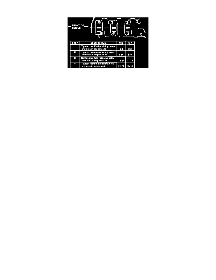
Fig. 2 Intake Manifold Bolt Tightening Sequence
1.
Disconnect battery ground cable.
2.
Remove air inlet hoses from air cleaner and throttle body.
3.
Disconnect throttle cable from linkage from throttle body.
4.
Remove throttle cable bracket attaching bolts, then position cable and bracket aside.
5.
Release fuel system pressure as follows:
a. Connect fuel pressure gauge (part No. T80L-9974-B) with extension hose (part No. D85L-9974-B) to Schrader valve on fuel supply manifold.
b. Position drain hose in a container and depress drain valve.
6.
Disconnect fuel lines from fuel supply manifold and pressure regulator.
7.
Disconnect the following electrical connectors and position aside: air charge temperature sensor, idle speed control valve, throttle position sensor
and engine coolant temperature sensor.
8.
Label, then disconnect vacuum hoses from intake manifold, manifold plenum and throttle body.
9.
Drain cooling system, then remove hose from thermostat housing to radiator.
10.
Unfasten and remove EGR tube from throttle body.
11.
Remove throttle body/plenum assembly attaching bolts and the assembly from intake manifold.
12.
Remove distributor cap and wires as an assembly, then disconnect distributor electrical connector.
13.
Mark position of distributor rotor and housing for assembly reference, then remove hold-down screw, clamp and the distributor assembly.
14.
Remove valve cover attaching bolts and the valve cover.
15.
Remove intake manifold attaching bolts and the intake manifold. Note length of attaching bolts for assembly reference.
16.
Reverse procedure to install, noting the following:
a. Apply sealant to manifold prior to gasket installation.
b. Ensure tab on right hand cylinder head gasket fits in cutout on intake manifold.
c. Hand-tighten retaining nuts onto studs 3 and 4, then torque retaining nuts and bolts as shown in Fig. 2.
d. Torque valve cover attaching bolts and EGR tube-to-throttle body attaching bolts to specification.
e. Torque throttle body/plenum assembly attaching bolts to specifications in two steps.