
Sable V6-182 3.0L (1986)
Constant Velocity Joint: Service and Repair
Inboard CV Joint
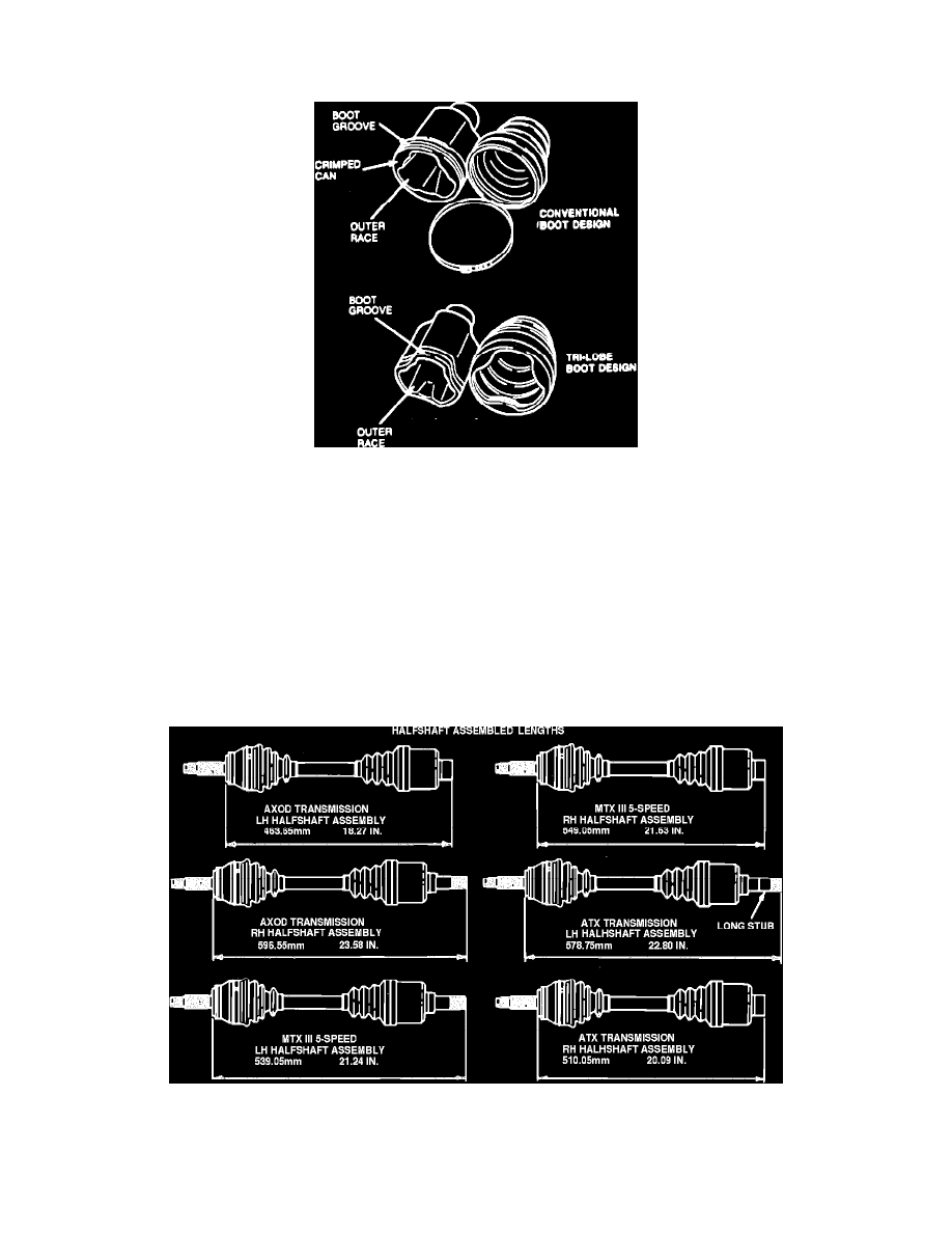
Fig. 14 CV joint identification
Disassembly
These models use two different types of inboard CV joints and boots, Fig. 14. The first one is of a conventional boot design that uses a crimped can on
the large end. The other is a tri-lobe design CV joint that does not require a crimped can on the large end. Although both designs are similar, there is no
interchangeability between them.
1.
Cut and remove both large and small boot clamps from CV joint, then slide boot back on shaft. All right side inboard CV joints use a reusable
low profile large boot clamp. Do not cut this clamp as it will be re-used.
2.
Slide outer race off tripod assembly. Inspect CV joint grease for contamination by rubbing a small amount between two fingers. Any gritty feeling
indicates contamination. If grease is contaminated, proceed with disassembly. If grease is not contaminated and joint was operating satisfactorily,
add grease and replace boot.
3.
Using suitable snap ring pliers, slide stop ring back on shaft.
4.
Slide tripod assembly back on shaft to provide clearance to circlip, then remove circlip, tripod assembly and boot.
Fig. 15 Halfshaft Assembled Length
Assembly
1.
Install CV boot on shaft. Ensure boot small end is seated properly in halfshaft groove, then tighten small end clamp.
2.
Install tripod assembly on shaft with chamfered side toward stop ring, then install new circlip. Circlips cannot be reused. They must be