
Sable V6-183 3.0L DOHC VIN S MFI (1997)
Electronic Brake Control Module: Service and Repair
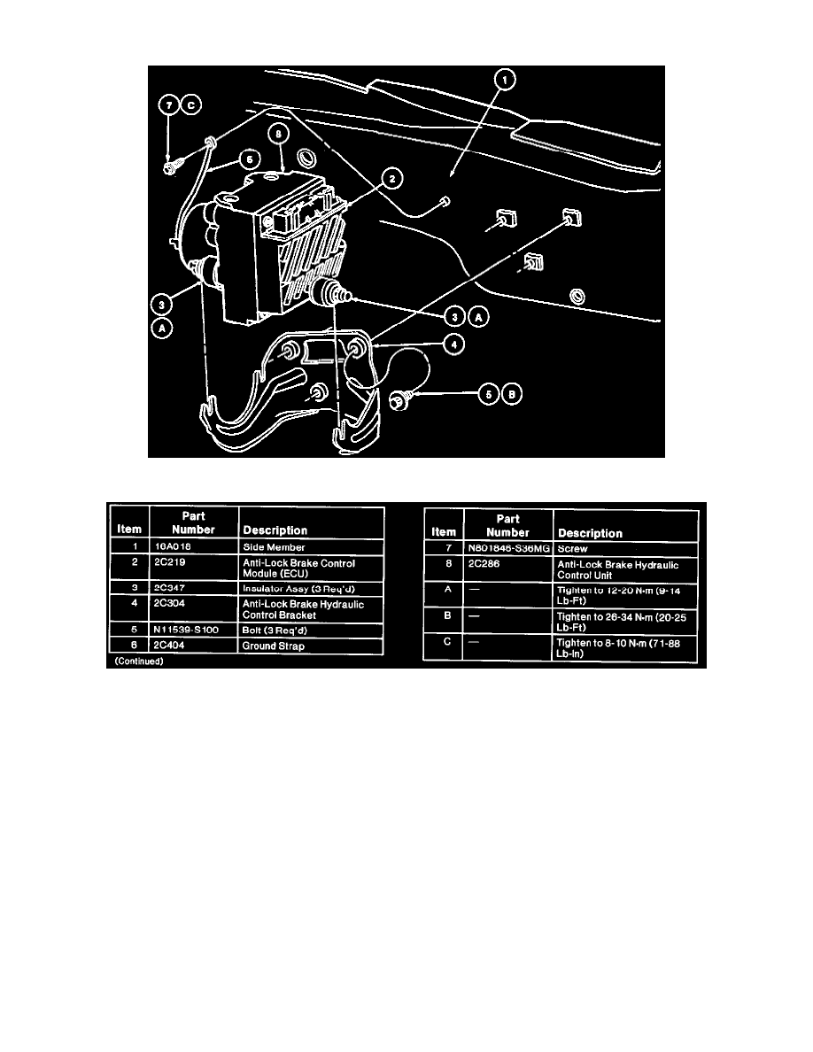
ABS HCU Mounting (Part 1 Of 2)
ABS HCU Mounting (Part 2 Of 2)
REMOVAL
1. Disconnect and remove battery from vehicle.
2. Remove battery tray and mounting bracket from vehicle.
3. Disconnect anti-lock brake wiring connector from anti-lock brake control module.
4. Remove two tubes from inlet ports and four tubes from outlet ports of anti-lock brake hydraulic control unit. Plug each port to prevent brake fluid
from spilling onto paint and wiring.
5. Remove body screw from anti-lock pump motor ground strap.
6. Remove three nuts retaining anti-lock brake control module assembly to anti-lock brake hydraulic control bracket (2C304) and remove assembly
from vehicle.
NOTE: Use caution removing control module from hydraulic control unit to avoid damage to the internal connector.
7. Remove five screws from anti-lock brake control module.
8. Remove anti-lock brake control module from anti-lock brake hydraulic control unit.
INSTALLATION
1. Position anti-lock brake control module onto anti-lock brake hydraulic control unit.
2. Install five screws.
3. Position anti-lock brake control module assembly into anti-lock brake hydraulic control bracket.
4. Install three retaining nuts and tighten to 16-24 Nm (12-17 ft.lbs).