
Sable V6-183 3.0L DOHC VIN S MFI (1997)
18.
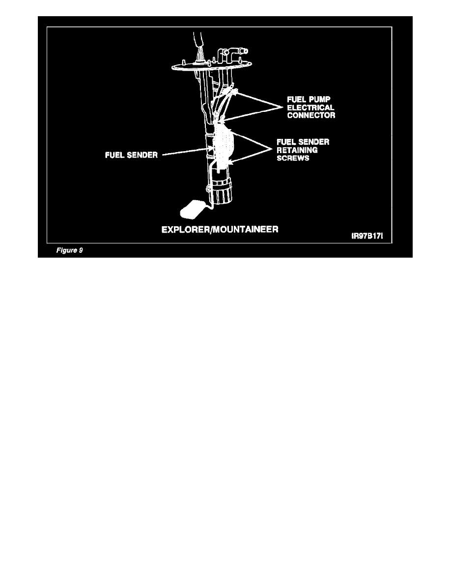
Disconnect fuel sender electrical connectors. Refer to Figure 9.
19.
Remove fuel sender retaining screws, then remove fuel sender. See Figure 9.
20.
Install new fuel sender on fuel pump. Tighten screws to 2 Nm (18 lb/in).
21.
Connect fuel sender electrical connectors. Make sure wires are routed correctly.
22.
Clean fuel pump-to-gas tank mating surface.
23.
Install fuel pump. Align marks made during disassembly. Tighten retaining screws to 9-12 Nm (80-107 lb/in).
24.
Connect fuel tank pressure transducer electrical connector.
25.
Position fuel tank under vehicle.
26.
Raise fuel tank enough to connect fuel lines.
27.
Connect fuel supply and return lines.
28.
Connect fuel pump electrical connector.
29.
Position fuel tank in installed position.
30.
Install fuel tank-to-front support bracket retaining bolts. Tighten bolts to 34-46 Nm (25-34 lb/ft).
31.
Install fuel tank strap retaining bolt. Tighten bolts to 34-46 Nm (25-34 lb/ft).
32.
Remove jack.
33.
Connect fuel filler and vent hoses to fuel tank.
34.
Install skid plate. Torque retaining bolts to 34-46 Nm (25-34 lb/ft).
35.
Lower vehicle.