
Sable V6-183 3.0L DOHC VIN S MFI (1997)
Multiplex Communication Network: Description and Operation
J1850 Communication Network
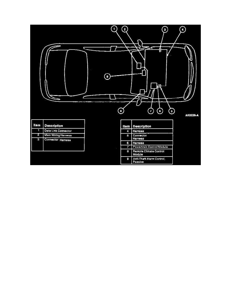
J1850 Network Component Location
The J1850 communication network provides:
^
The ability for module-to-module communication by sharing required inputs and outputs instead of each component having an input or output
wired directly to or from each affected module.
^
A common link for communication to an off-board tester through the Data Link Connector (DLC) located under the instrument panel to the right
of the steering column.
Three micro-processor based subsystems are included on this network:
^
Powertrain control
^
Passive anti-theft
^
Climate control
The communication bus between these subsystems and the DLC consist of an unshielded twisted pair of wires:
^
Circuit 914 (T/O) Bus+
^
Circuit 915 (PK/LB) Bus-
Fault Tolerance
The J1850 communication network will remain operational in the event:
^
One circuit is severed.
^
One circuit is shorted to ground.
^
One circuit is shorted to battery positive voltage (B+).
^
A termination resistor is lost within a module.
^
One or more modules fail internally.
Any of these conditions will be detected and reported to the off-board tester during diagnostics in the form of a DTC.
Purpose