
Sable V6-183 3.0L DOHC VIN S MFI (1997)
Fluid Pump: Service and Repair
Installation
Pump Assembly And Main Control Valve Body Installation
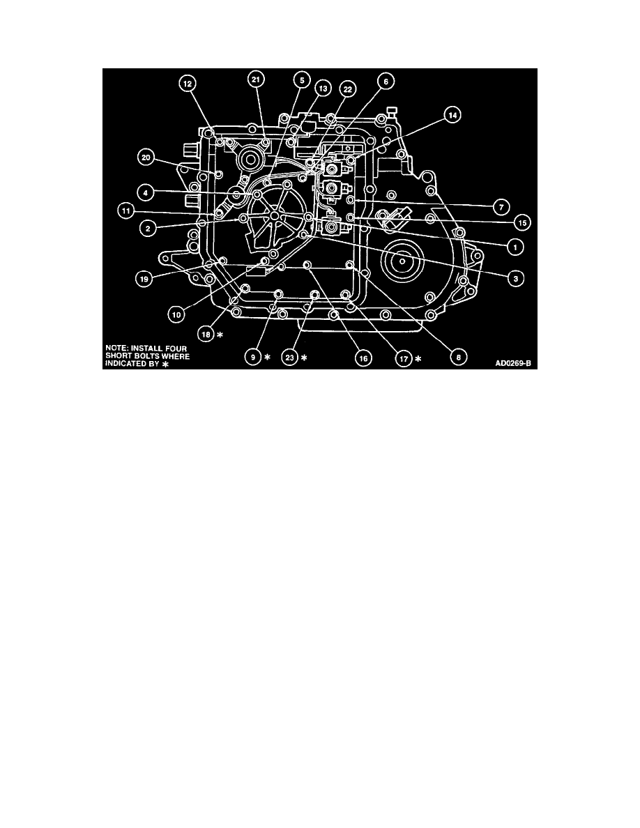
1. Install a new pump assembly and new main control valve body-to-chain cover gasket onto chain cover.
2. Carefully slide pump assembly and main control valve body over pump shaft and onto chain cover.
3. Install pump assembly. Vehicles equipped with an Anti-Lock Brake System (ABS) only.
NOTE: On vehicles equipped with ABS, the hydraulic modulator may not afford enough clearance to sufficiently rotate the pump assembly and
main control valve body to complete engagement between the pump shaft and pump assembly. It may be necessary to rotate the crankshaft using a
7/8 inch deep well socket on the crankshaft pulley to complete the engagement of the pump shaft with the pump assembly. If the vehicle is not
equipped with ABS, the following procedure may be used to obtain pump shaft engagement with the pump assembly.
a. Remove manual shift valve from main control valve body.
b. Rotate the main control valve body as necessary to allow engagement between the pump shaft and pump assembly. If complete engagement
has been obtained, the main control valve body should slide flush onto chain cover with little effort.
c. After full engagement between the pump shaft and pump assembly has been obtained, align main control valve body to installation position
and install manual shift valve.
4. Rotate pump assembly and main control valve body clockwise and connect manual valve link with manual shift valve.
CAUTION: Do not use pump assembly and main control valve body bolts to draw pump assembly and main control valve body onto chain cover
or component damage may result.
6. Install transaxle wiring harness into chain cover.
7. Connect transmission fluid temperature sensor and solenoid electrical connectors to solenoids and main control valve body.
8. Install transaxle side pan with new gasket to chain cover. Secure transaxle side pan with transaxle side pan bolts and tighten to 9-12 Nm (80-106
inch lbs.).
9. Install LH engine support and insulator.
10. Install LH front fender splash shield.
11. Install LH front wheel tire and wheel assembly.
12. Lower vehicle.
13. Remove Rotunda Three Bar Engine Support D88L-6000-A or equivalent and Engine Lifting Eye Set.
14. Install RH cowl assembly.
15. Connect Transmission Range (TR) sensor and transaxle harness electrical connectors and position engine wire harness.
16. Install battery and battery tray.
17. Connect battery ground cable and positive battery cable.
18. Install Air Cleaner (ACL) assembly.