
Tracer L4-110 1.8L DOHC (1995)
Hydraulic Control Assembly - Antilock Brakes: Service and Repair
1. Remove battery tray, then the acid shield.
2. Tag and disconnect electrical connectors, then tag brake tubes and mark corresponding ports.
3. Remove brake tubes from hydraulic anti-lock actuator assembly.
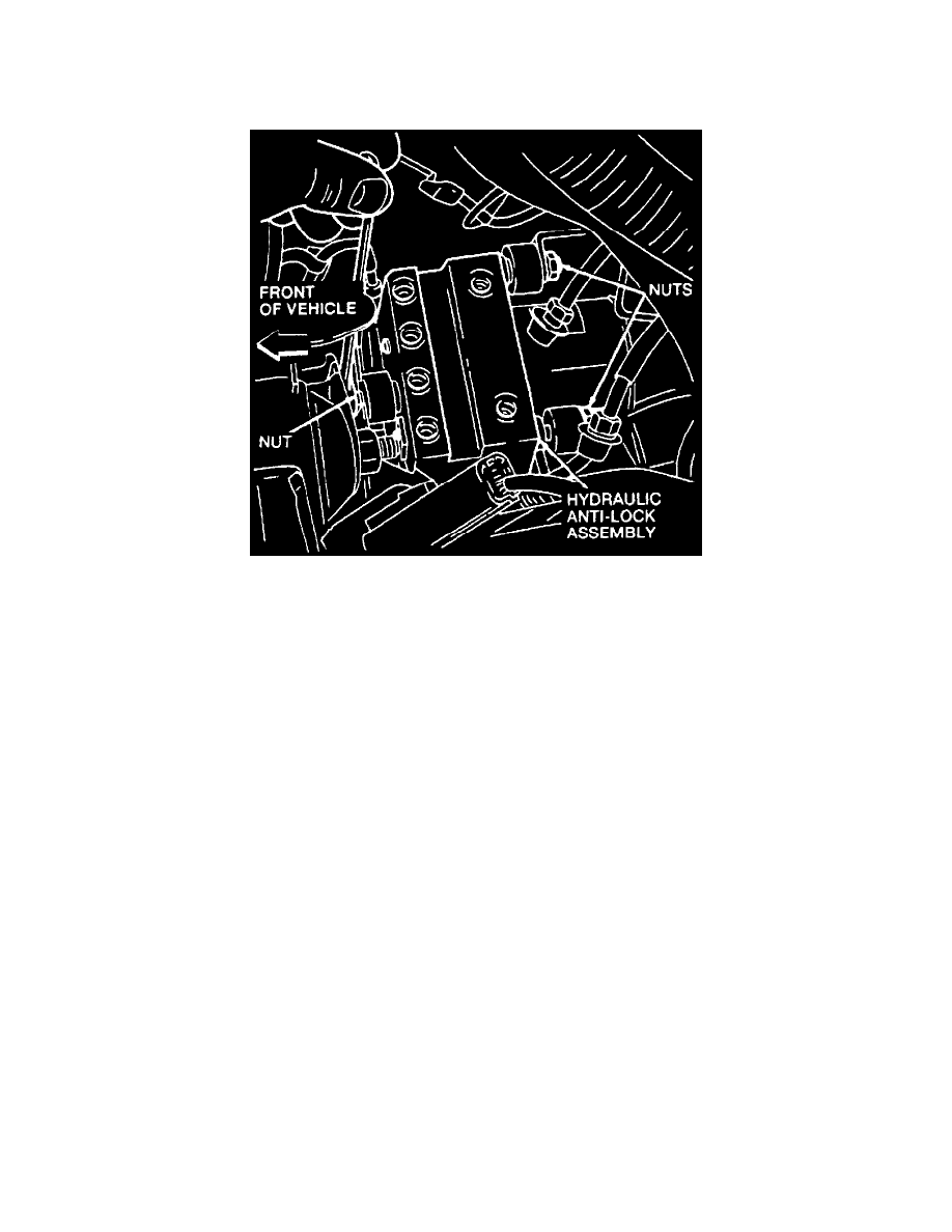
Fig. 62 Hydraulic Anti-Lock Actuator Assembly Removal
4. Loosen nut on front of actuator assembly, then the two nuts on back of actuator assembly.
5. Remove actuator assembly.
6. Reverse procedure to install.
7. Ensure electrical connectors are properly routed.
8. Torque brake tube fittings to 10-16 in lb.
9. Perform system brake bleeding procedures.