
Villager V6-201 3.3L SOHC VIN T SFI (1999)
Vacuum Brake Booster: Description and Operation
The power brake booster uses engine vacuum for operation. The applied force created when the brake pedal is depressed is mechanically increased
with the assistance of the engine vacuum. Power brakes reduce the amount of pedal pressure necessary to stop the vehicle, as well as reducing brake
pedal travel (the distance from the release position to full brake application).
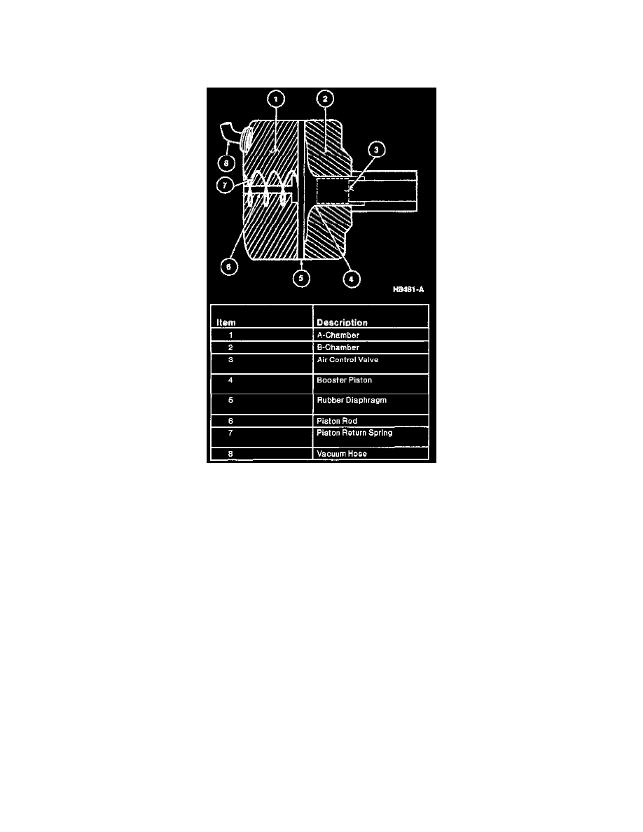
The power brake booster is divided into two chambers by a rubber diaphragm. The A-chamber is on the master cylinder side (front) of the power
brake booster, and the B-chamber is on the brake pedal side (rear) of the power brake booster. A vacuum exists in both chambers when the brake
pedal is in the released position. When the brake pedal is depressed, the air control valve is forced against the booster piston seat. This action closes
the vacuum valve between the two chambers, and the vacuum to the B-chamber (rear) is cut off. As the brake pedal is further depressed, the air control
valve allows atmospheric pressure to enter the B -chamber. This creates a pressure difference between the two chambers. This pressure difference
causes the diaphragm, booster piston and air control valve to move forward into the A-chamber, pushing the piston rod into the brake master cylinder
and applying pressure to the braking system.
When the brake pedal is released, the booster piston return spring forces the diaphragm, booster piston and air control valve rearward, closing the air
intake valve and opening the vacuum valve between the two chambers. A common vacuum now exists between the two chambers again.