
Sigma V6-2972cc 3.0L SOHC (1989)
Crankshaft Position Sensor: Description and Operation
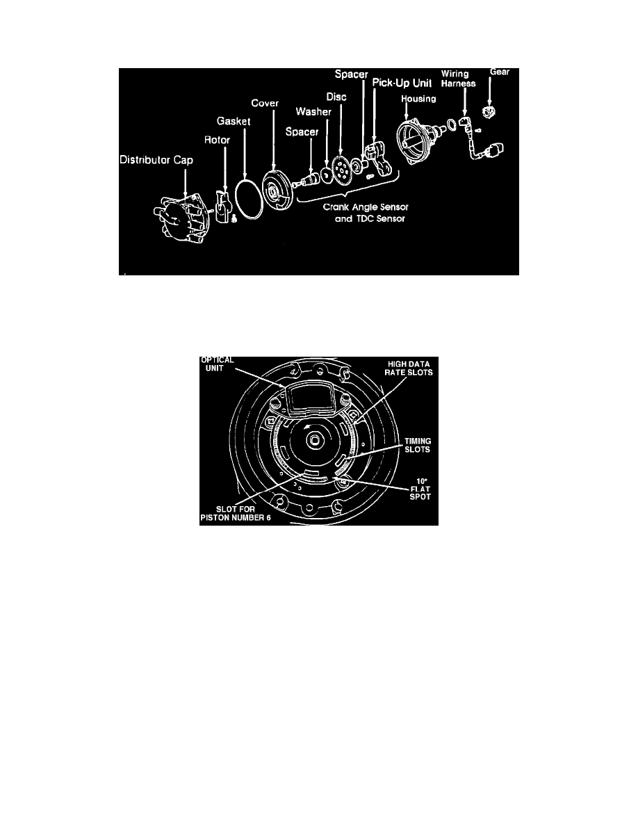
Distributor (Crank Angle and #1 TDC Sensors)
Distributor Exploded View
The Distributor consists of a housing, shaft, drive gear, distributor cap and rotor, and houses the crankshaft angle and the No.1 cylinder TDC sensors.
The drive gear (mounted on the end of the distributor shaft) drives the shaft at cam shaft speed. On the other end of the shaft the rotor is mounted. When
properly timed the rotor carries current from the coil tower in the distributor cap to the correct spark plug electrode for the designated firing order.
Crank Angle And #1 TDC Sensor
The crankshaft angle sensor and the No.1 cylinder TDC sensor are composed of a disc and optical unit assembly. The disc contains 360 slits around its
circumference to indicate the crankshaft angle. An additional six light-transmission slits located 60° apart located inward from the edge are used to
indicate each cylinder's top dead center position. The pick-up unit assembly uses two luminous diodes and two photo diodes, in order to be able to detect
the two different slits. There is a very slight clearance between the luminous diodes and the photo diodes, and the disc rotates within this space. As the
distributor shaft rotates the slits at the discs edge pass between the light and the optical reading part of the unit. The light emitted from the luminous
diodes pass through the slits to the photo sensing diodes. When the photo diodes receive the light, they become conductive and generate a signal, which
is sent to the Control Unit.
Crankshaft Angle Signal:
Top dead center is detected by the signal obtained from the outer series of slits (1° slits) by reading the 10° blank spot. The ECU, based upon this signal,
determines which of the six pulses from the TDC sensor is the signal for the No.6 cylinder (reference cylinder), thus synchronizing the ECU with the
rotation of the disc in the distributor. This allows the ECU to determine (with the use of its preset firing order) which pulse is the No.1 cylinder. The
outer circumference slits are also used by the ECU to assist in a more accurate ignition timing at engine speeds below 1200 rpm. The Control Unit is able
to detect number one cylinder TDC by the comaring the signal generated through the inner slits on the disc and the blank space on the outer slits and
calculating the position.
No.1 Cylinder TDC Signal:
The six slits located at the inner circumference of the disc serve to detect the position of the pistons relative to top dead center. The ECU, based on this