
Ciera V6-173 2.8L VIN W FI (1986)
Brake Fluid Pressure Sensor/Switch: Customer Interest
Brakes - Longer Pedal Travel
SUBJECT:
LONGER BRAKE PEDAL TRAVEL (DIAGNOSIS AND REPAIR PROCEDURE)
MODELS/YEARS:
1985-86 CUTLASS CIERA, FIRENZA, CALAIS MODELS
AND 1985 NINETY-EIGHT MODELS EQUIPPED WITH DIAGONAL SPLIT MASTER CYLINDER AND BRAKE
PRESSURE WARNING SWITCH
NUMBER:
86-T-74
CORP. REF. NO: 875007R
DATE:
January 1989
SECTION:
5
Some customers may comment about a longer brake pedal travel condition, which is usually corrected by bleeding the brake system. In any case where
this condition is repeated, the wiring to the brake pressure warning switch should be checked.
If the wiring to the brake pressure warning switch connector is reversed, the polarity of the brake pressure warning switch will also be reversed (even
though the switch is not defective), and a small current may flow thru the brake fluid. This may cause some of the fluid to gasify, creating bubbles in the
fluid which will act like air in the system. If enough gas accumulates in the brake hydraulic system, the brake warning lamp may come on.
Note:
If this condition is present, noticeable accumulation of gas in the brake hydraulic system will take place over a long period of time, resulting in
a very gradual change in brake pedal feel.
To test for this condition, perform the following steps:
1.
Start the vehicle and observe the instrument panel for brake warning lamp operation. The brake warning lamp must be functioning properly before
proceeding further with diagnosis. Repair of the lamp may involve bulb replacement and/or circuit diagnosis.
ILLUSTRATION
2.
If the brake warning lamp operates correctly, proceed as follows:
a.
Disconnect the connector from the switch.
b.
Set the ignition switch to RUN position.
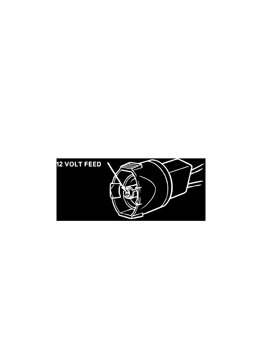
c.
With a test light, probe the center terminal of the connector with one lead and ground the other lead to a chassis ground (NOT the
connector ground). If the test light illuminates, indicating current flow, the polarity is correct. See illustration.
d.
If the test light does not light when probing the center terminal of the connector, probe the grounding ring of the terminal with one lead and
ground the other lead to a chassis ground. If the test light illuminates, indicating current flow the polarity is reversed, and should be
corrected by:
-
Cut the wires at the connector, reverse them, and splice using a solder connection.
-
Properly seal the splice with tape.
The brake hydraulic system should then be completely bled.
Warranty Information