
Cutlass V6-191 3.1L VIN M SFI (1998)
CIRCUIT DESCRIPTION
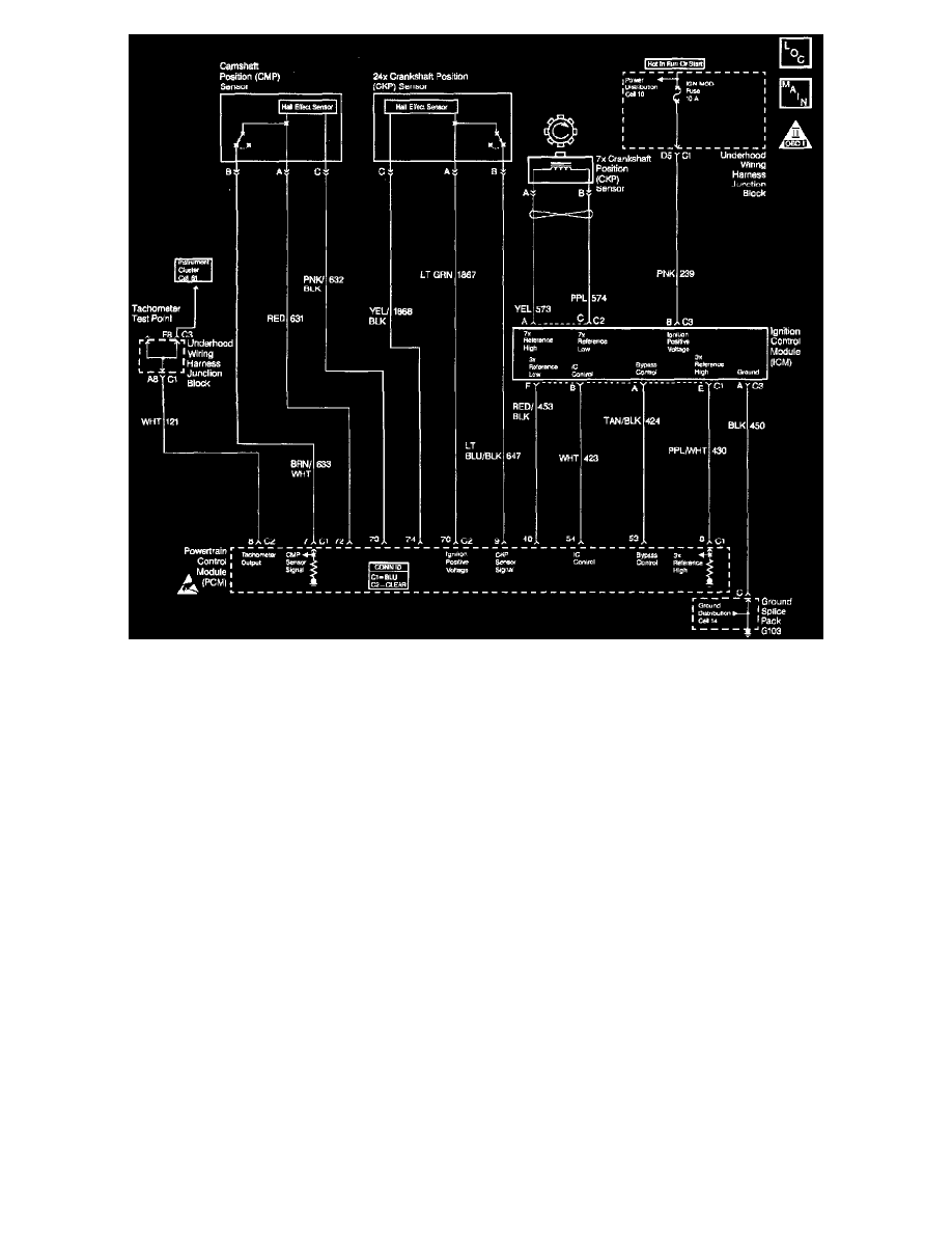
The PCM supplies the ground to energize the Instrument Cluster tachometer. When the ignition switch is first turned on the PCM grounds the tachometer
circuit. The circuit will remain grounded until the PCM receives the first 24X reference pulse. Once the 24X reference pulse is received, the PCM
controls the pulse frequency in relationship to engine RPM. The tachometer is controlled at a rate of two pulses per crankshaft revolution.
DIAGNOSTIC AIDS
Check for the following conditions:
^
Poor connection at the PCM or instrument cluster. Inspect the harness connectors for backed out terminals, improper mating, broken locks,
improperly formed or damaged terminals, and poor terminal to wire connection.
^
Damaged harness. Inspect the wiring harness for damage. If the harness appears to be OK, disconnect the PCM, turn the ignition ON and
observe voltmeter connected to the tachometer control circuit at the PCM harness connector while moving connectors and wiring harnesses
related to the tachometer control circuit. A change in voltage will indicate the location of the fault.
TEST DESCRIPTION
Number(s) below refer to the step number(s) on the Diagnostic table:
3. Normally, ignition feed voltage should be present on the output driver circuit with the PCM disconnected and the ignition turned on.
4. Checks for a shorted component or a short to battery positive voltage on the output driver circuit. Either condition would result in a measured
current of over 0.5 amps.
5. Checks for a faulty instrument cluster.
14. A fault in the 24X/Camshaft position sensors feed or ground circuits will result in the loss of both PCM input pulses. Without a 24X reference
pulse the PCM can not begin tachometer pulse control causing an inoperative tachometer.