
Ninety-Eight V6-3800 3.8L Supercharged (1993)
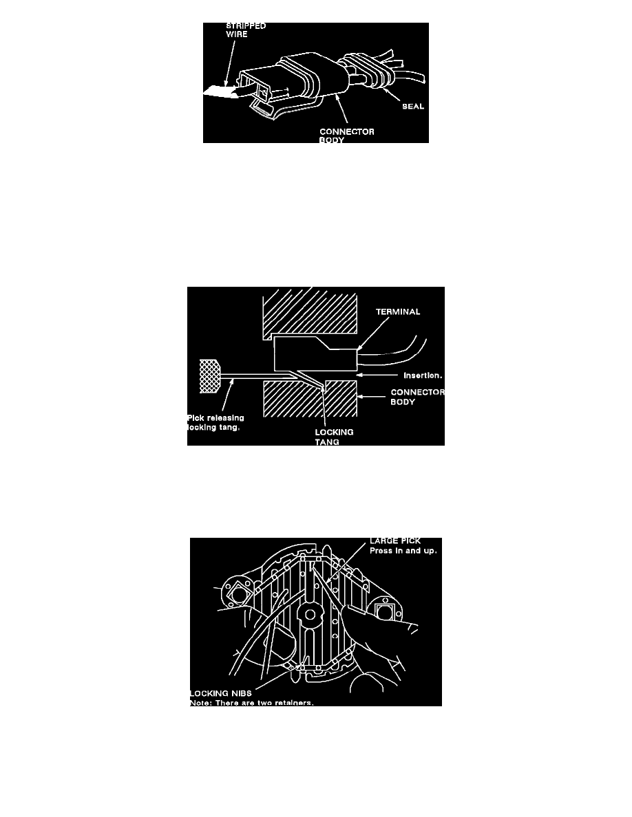
Figure 23
c.
Strip 5 mm (3/16") of insulation from the wire (see Figure 23).
d.
Crimp new terminal to wire.
e.
Solder with rosin core solder.
f.
Carefully pull on wire to draw terminal into connector body until it locks.
Push-to-Seat Connectors
NOTE: The following general repair procedures can be used to repair most types of connectors. Use the Pick(s) or Tools that apply to your terminal.
Use Terminal repair kit J 38125 or equivalent.
Figure 1 - Typical Push-To-Seat Connector
Follow the steps below to repair Push-To-Seat connectors (Figure 1). The steps are illustrated with typical connectors. Your connector may be different,
but the repair steps are similar. Some connectors DO NOT require all the steps shown. Skip the steps that DO NOT apply.
Remove Terminal Position Assurance (TPA) device, Connector Position Assurance (CPA) device and/or secondary lock.
Figure 2