
Ninety-Eight FWD V6-181 3.0L (1985)
Then lay a second new 1" X 24" insulator strip from the kit, part number 22530899, over each of the original ones so as to double strip each cavity
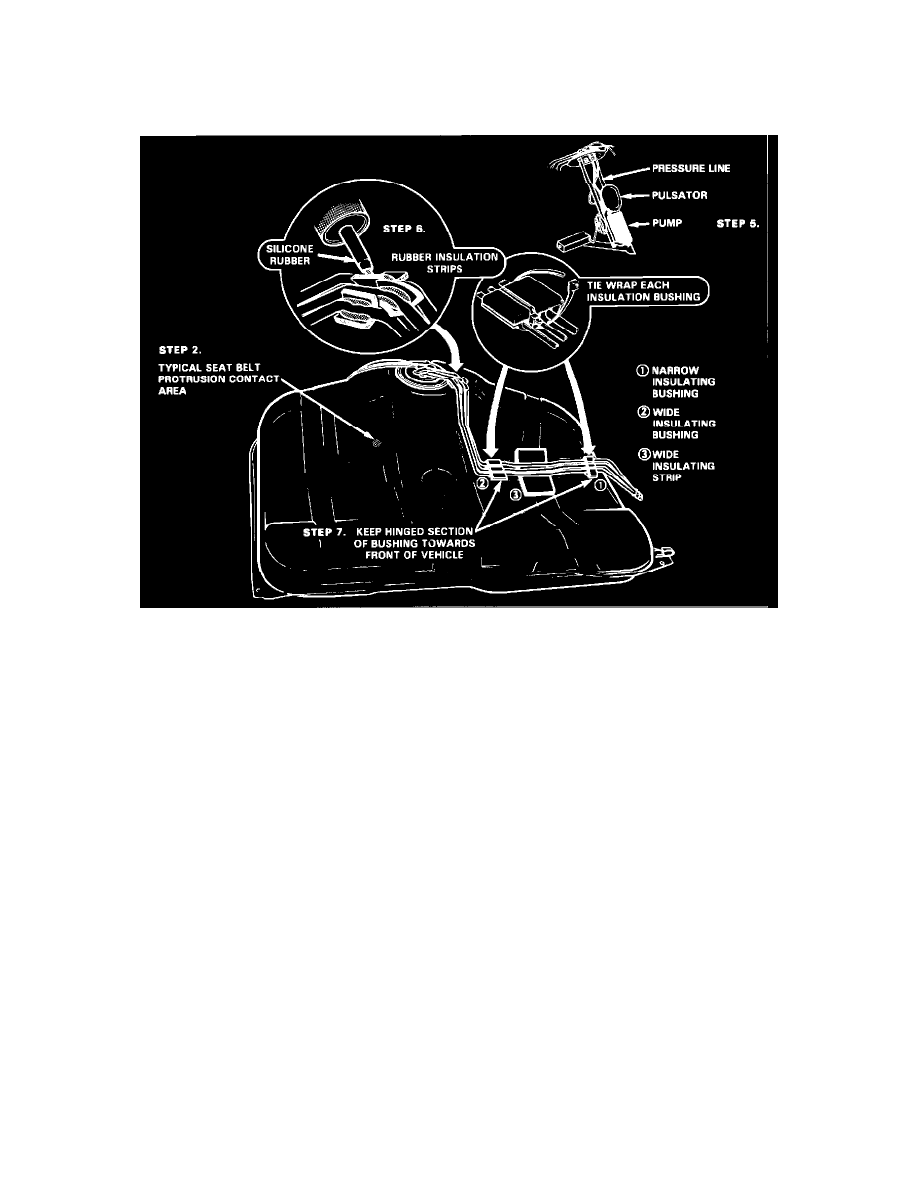
insulator strip, without cutting off the area over the drain plug (see Figure 1).
4.
Remove the pads from both seat belt anchor protrusions and reinstall the 2" X 6" pad on the right seat belt anchor protrusion and the 2" X 2" along
with one new 2" X 2" from the kit on the left seat belt protrusion. Secure pads in place with duct tape (see Figure 1).
FIGURE 2
5.
Remove fuel pump and sender assembly and replace pulsator, part number 6472359. Inspect pump part number as described previously and
replace as necessary. Check that the pump is not bottoming out on the tank bottom by removing the O-ring and reinstalling the pump and sender
assembly in the tank and noticing if sender cover rests on the O-ring seat. If the sender cover does not rest on the O-ring seat of the tank, the pump
might be bottomed out on the tank bottom. Repair as necessary. Install new fuel sender O-ring, part number 22515965, and reinstall fuel pump and
sender assembly in tank (see Figure 2).
6.
Examine steel sender lines at bend near the tank opening. They must not contact one another or the fuel tank. If possible, separate the tubes, taking
care not to damage or deform tubes or break solder connection at sender cover. If required, cut rubber strips and fit them between and under the
pipes to eliminate metal to metal contact. Prior to installing tank, apply silicone rubber sealer to rubber strips to permanently hold them in position
(see Figure 2).
7.
Position the new wide and narrow insulation bushings from the kit, as shown, making sure the hinged portion of the bushing is toward the front of
the vehicle. Place the one wide insulator strip under the center of the curved portion of the fuel lines. This wide insulator strip will not allow the
pipes to contact the top of the fuel tank. Position the narrow insulator bushing close to the groove in the tank at the extreme driver side of the fuel
tank making sure all lines lie flat.
To assist in providing for positive positioning of the insulation bushings, place a small amount of silicone rubber in the grooves of each bushing.
Then insert the tubes in the bushing. Tiewrap the assembly twice, locating the lock tabs to the side (see Figure 2).