
Omega L4-151 2.5L VIN 5 2-bbl (1982)
Lifter / Lash Adjuster: Description and Operation
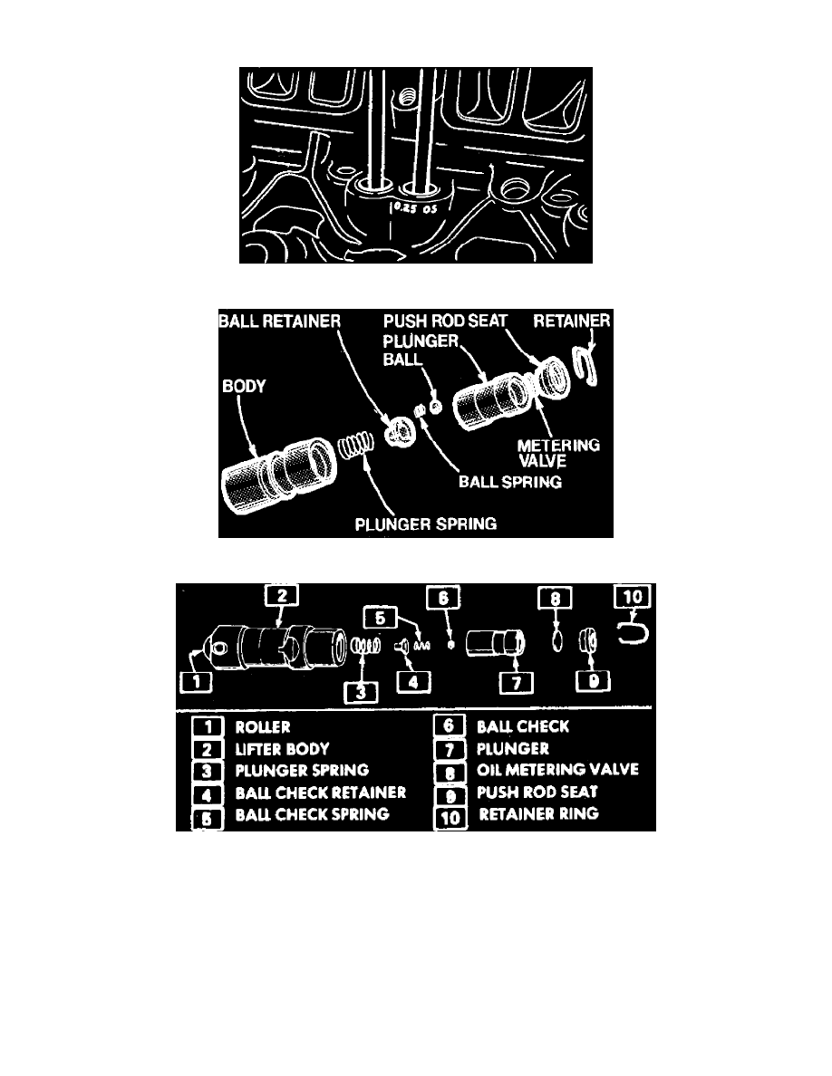
Fig. 10 Oversize valve lifter marking. V6-173
Fig. 11 Flat type hydraulic lifter exploded view
Fig. 12 Roller type hydraulic lifter exploded view
Some V6-173 engines will be equipped with both standard and .25 mm. oversize valve lifters. The cylinder case will be marked where the oversize
valve lifters are installed with a daub of white paint and .25 mm. O.S. will be stamped on the valve lifter boss, Fig. 10.
Failure of a hydraulic valve lifter, Figs. 11 and 12, is generally caused by an inadequate oil supply or dirt. An air leak at the intake side of the oil
pump or too much oil in the engine will cause air bubbles in the oil supply to the lifters, causing them to collapse. This is a probable cause of trouble if
several lifters fail to function, but air in oil is an unlikely cause of failure of a single unit.
On 4-151 engines, valve lifters can be removed after removing rocker arm cover, intake manifold, push rod cover and push rod retainer and guide, if
applicable. Loosen rocker arm stud nut and rotate rocker arm so that push rod can be removed, then remove valve lifter. It may be necessary to use tool
No. J-3049 to facilitate lifter removal.
On V6-173 engines, valve lifters can be removed after removing rocker arm covers, intake manifold, rocker stud nuts, rocker arm balls, rocker arms