
Toronado V6-231 3.8L (1986)
Carburetor: Description and Operation
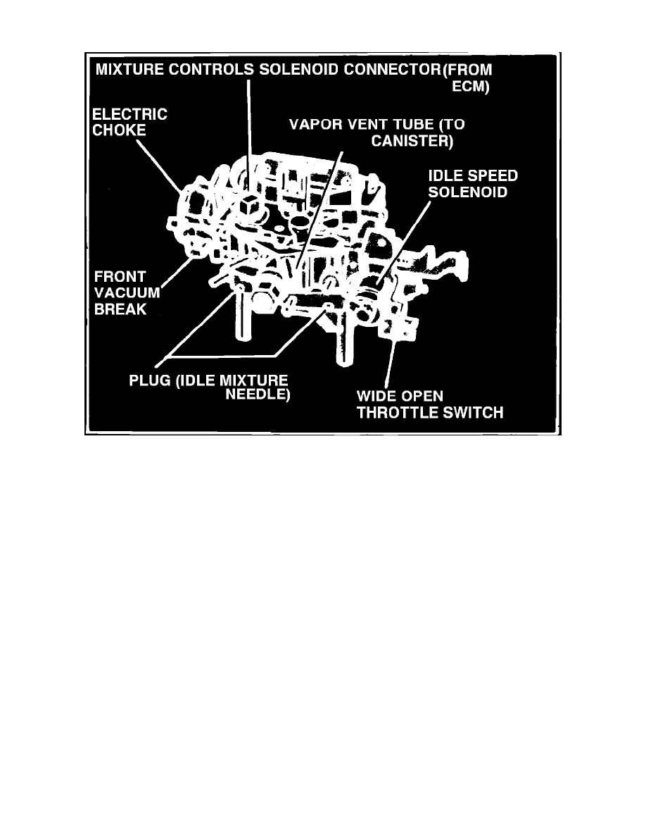
Fig. 2 Rochester Dual-Jet model E2ME
The Dual Jet carburetor, Fig. 2, is a two barrel, single stage unit, incorporating the design features of the primary side of the Quadrajet (four barrel)
carburetor. The triple venturi stack up, plus the smaller 13/8 inch bores result in good fuel metering control during all phases of operation.
The main metering system has a separate main well for each main nozzle for good fuel flow through the venturi.
An electrically operated mixture control solenoid, mounted in the fuel bowl, is used to control the fuel-air mixture metered to the idle and main
metering systems. Fuel metering is controlled by two stepped metering rods positioned by a plunger in the mixture control solenoid. The solenoid
plunger is controlled or ``Pulsed'' by an electrical output signal from the Electronic Control Module (ECM). The ECM, responding from a signal from
the oxygen sensor, energizes the solenoid, to move the plunger and metering rods to control fuel delivery to the idle and main metering systems. At the
same time, air metering to the idle system is controlled by an idle air bleed valve, located in the air horn, which follows movement of the mixture control
solenoid plunger to control the amount of air bleed into the idle system to lean or richen the mixture. The movement or ``Cycling'' of the solenoid
plunger occurs approximately 10 times per second, thereby controlling the fuel-air mixture to achieve optimum mixture ratios. The positioning of the
mixture control solenoid in the float bowl, rich stop setting and idle air bleed valve in the air horn are factory adjusted and no attempt should be made to
alter these settings except during major carburetor overhaul or when air horn or float bowl replacement is necessary.
On some E2M units, an idle speed control mounted on the float bowl is used to control idle speed. On these units, the curb idle speed is programmed
into the Electronic Control Module and no attempt should be made to adjust idle speed.
The choke cover is retained to the choke housing by three pop rivets. With float bowl and throttle body properly supported, carefully align a No. 21
drill on pop rivet head. Drill only deep enough to remove rivet head, then using a small hammer and drift, drive remainder of rivet from choke housing.
A service kit is available for choke cover installation. The choke cover should be removed only during major carburetor overhaul or if the choke coil is
damaged.