
405 L4-1905cc 1.9L (1989)
7.
Install lower and upper return springs and secure to brake shoes.
8.
Install brake drum, wheel and tire assembly.
9.
Actuate brake pedal several times to set the automatic adjuster.
10.
Check master cylinder fluid level and replenish as necessary.
11.
Check brake pedal for proper feel and return.
12.
Lower vehicle and road test.
Type 2
REMOVAL
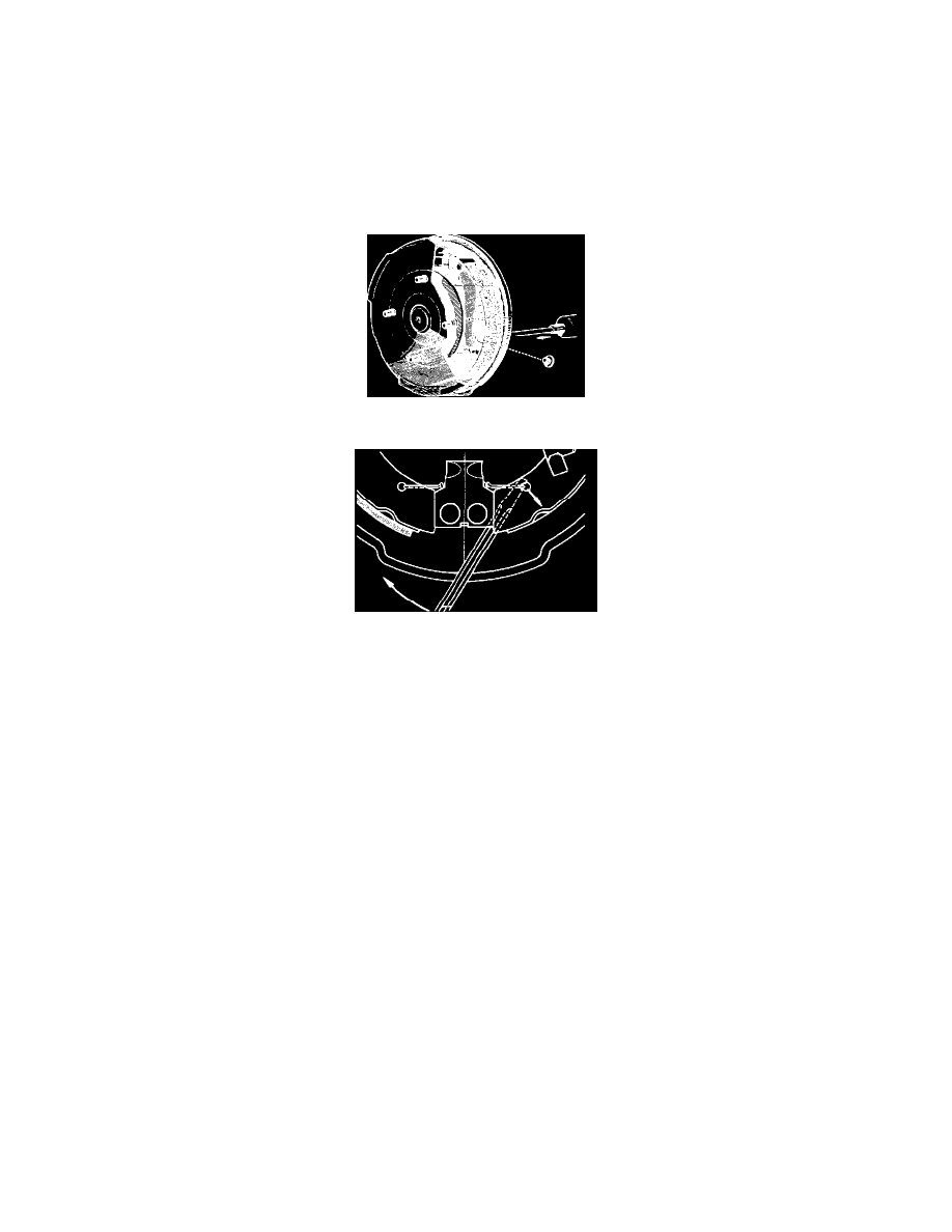
Fig. 1 Releasing Brake Shoes
Fig. 2 Lower Return Spring. Girling & DBA Type 2 Brakes
1.
Raise and support rear of vehicle, then remove wheel and tire assembly.
2.
Loosen parking brake cable locknuts, then remove adjusting nuts.
3.
Remove plug from drum, Fig. 1, then insert a screwdriver through backplate and move parking brake lever outward to release brake shoes.
4.
Reinstall plug, then remove drum.
5.
On sedan models, remove lower return spring, Fig. 2.
6.
On all models, remove upper return spring, then position a clamp on brake cylinder.
7.
Remove hold-down springs, then the leading shoe.
8.
Disconnect parking brake cable from lever, then remove trailing shoe with link rod.
9.
Remove parking brake lever, automatic adjuster and pivoted control lever from brake shoes.
INSPECTION
1.
Clean drum and back plate with specified solvent.
2.
Check for proper sealing of the pistons.
3.
Inspect rubber boots for wear or damage.
4.
Check drum for excessive wear and grind if necessary.
5.
Check that automatic adjuster assembly bolt turns freely.
6.
Ensure automatic adjuster nut faces slight resistance when turned clockwise and much greater resistance when turned counterclockwise.
7.
Replace any damaged or excessively worn components.
INSTALLATION
1.
Lightly lubricate brake shoe pressure pads on back plate.
2.
Cover automatic adjuster bolt threads with a protective sleeve, .670 inch (17mm) long on sedan models, or .945 inch (24mm) long on wagon
models.
3.
Insert adjuster bolt into pawl, then slide ratchet guide into pawl groove.
4.
Install automatic adjuster control lever to adjuster lever, then secure return spring to adjuster.
5.
Attach automatic adjuster assembly to leading brake shoe using a new locking ring.
6.
Attach parking brake lever to trailing brake shoe.
7.
Attach hooked end of link rod to parking brake lever, then lock assembly by sliding support spring under yoke plate and inserting tab in hole in
lever.
8.
Connect parking brake cable to lever, then install trailing shoe to backplate.