
405 L4-1905cc 1.9L (1989)
Charging System: Description and Operation
Component Operation
Alternating current is generated by the stator as the field rotates. The rectifier bridge (trio-diode) changes the alternating current to direct current.
The amount of DC voltage produced by the alternator is controlled by the regulator. When the alternator output voltage is low, the regulator increases
current flowing through the field. This increases the alternator's output voltage (at terminal B+). Field current is supplied directly from the stator's output
through the trio-diode. This voltage provides initial field current for alternator output.
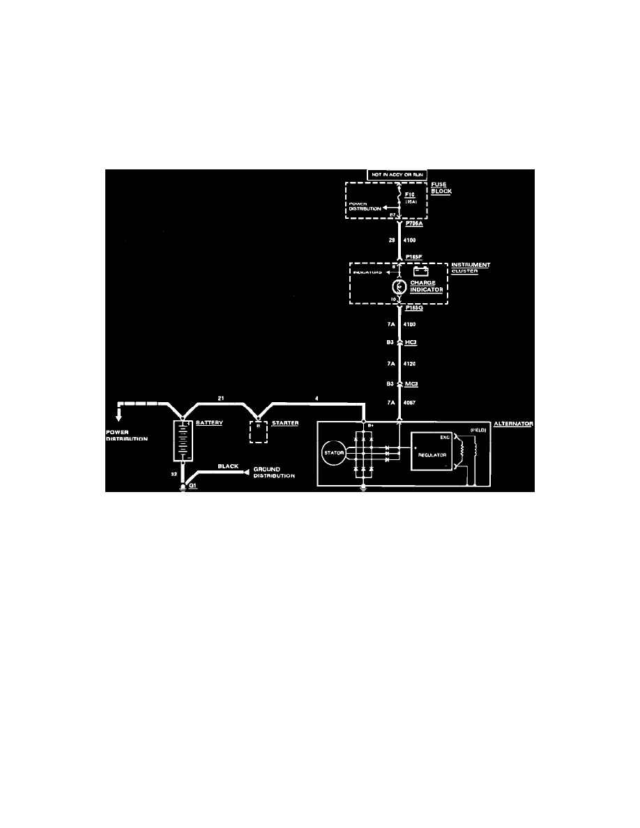
With the ignition switch in ``run'' position, and the engine not running, battery voltage is applied through fuse F10 to the charge indicator. The charge
indicator will illuminate.
Fig. 1 Wiring Circuit
With the ignition switch in ``run'' position and the engine running, the alternator output voltage, which equals the battery voltage, is applied through wire
No. 7, Fig. 1, to the charge indicator lamp. Battery voltage is applied through fuse F10 to the charge indicator lamp. With equal voltage on both sides of
the lamp, the lamp goes out.