
Breeze L4-2.4L VIN X (2000)
Output Speed Sensor - Automation Transaxle
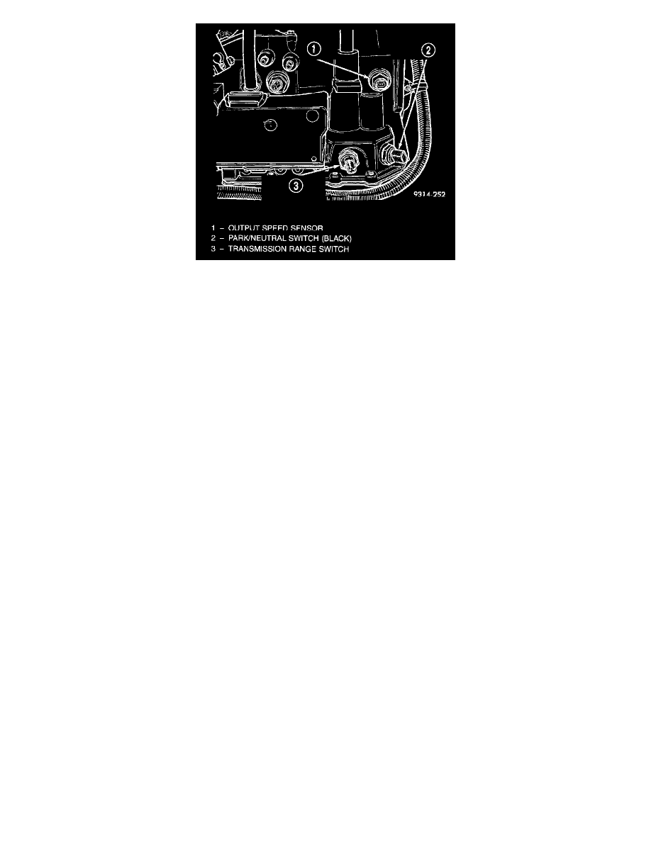
The TCM switches this signal to a ground, and then opens the circuit at a rate of 8000 pulses per mile. When the PCM counts 8000 pulses, the
PCM assumes the vehicle has traveled one mile. The output speed sensor is located on the side of the transaxle.
The speed and distance signals, along with a closed throttle signal from the TPS, determine if a closed throttle deceleration or normal idle
condition (vehicle stopped) exists. Under deceleration conditions, the PCM adjusts the idle air control motor to maintain a desired MAP value.
Under idle conditions, the PCM adjusts the idle air control motor to maintain a desired engine speed.
Manual
The sensor input is used by the PCM to determine vehicle speed and distance traveled.
The vehicle speed sensor generates 8 pulses per sensor revolution. These signals, in conjunction with a closed throttle signal from the throttle
position sensor, indicate a closed throttle deceleration to the PCM. Under deceleration conditions, the PCM adjusts the Idle Air Control (IAC)
motor to maintain a desired MAP value.
When the vehicle is stopped at idle, a closed throttle signal is received by the PCM (but a speed sensor signal is not received). Under idle
conditions, the PCM adjusts the IAC motor to maintain a desired engine speed.
The vehicle speed sensor signal is also used to operate the following functions or systems:
-
Speedometer
-
Speed control
-
Daytime Running Lights (Canadian Vehicles only).