
Colt L4-1597cc 1.6L DOHC (1990)
Rocker Arm Assembly: Service and Repair
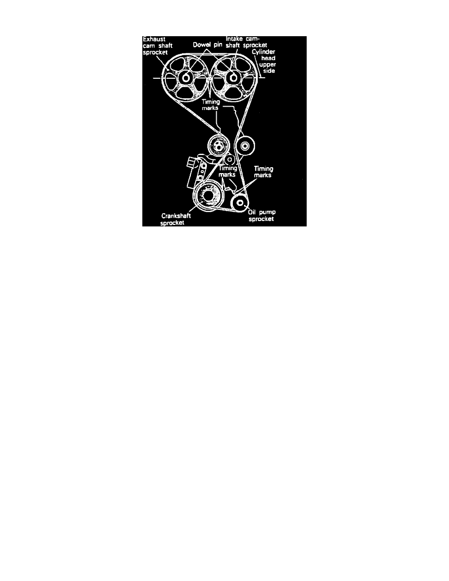
Fig. 5 Aligning Timing Marks
REMOVAL
1.
Disconnect battery ground cable.
2.
Disconnect accelerator cable from throttle body.
3.
Remove timing belt as follows:
a. Remove undercover.
b. Using a wood block and a jack, place wood block on engine oil pan and raise engine only enough to relieve tension on top engine mount, then
remove mount and bracket.
c. Remove engine drive belts. Prior to removing water pump drive belt, loosen water pump pulley bolts.
d. Remove crankshaft pulley.
e. Remove upper and lower timing covers.
f.
Remove tensioner pulley and bracket.
g. Disconnect PCV and breather hoses, then remove center cover, spark plug wires and rocker cover.
h. Rotate crankshaft clockwise to bring No. 1 cylinder to top dead center of compression stroke. Rotate crankshaft only in clockwise direction.
The No. 1 cylinder is at top dead center of compression stroke when the timing marks on camshaft sprockets are aligned with upper surface of
cylinder head and dowel pins on camshaft sprockets are facing up as shown,.
i.
Remove auto tensioner.
j.
Mark timing belt indicating direction of rotation, then remove timing belt.
4.
Remove throttle body support bracket.
5.
Remove crankshaft angle sensor from rear of intake camshaft.
6.
Remove camshaft sprockets as follows:
a. Using a wrench at the hexagonal part of the camshaft (to prevent the camshaft from turning) loosen, then remove the camshaft sprocket bolts
and camshaft sprockets.
7.
Using a screwdriver or suitable tool, remove camshaft oil seals. Use caution not to damage front camshaft bearing caps or camshafts.
8.
Loosen camshaft bearing cap bolts in two or three steps, then remove bolts and bearing caps. If bearing caps are difficult to remove, use a
plastic hammer to lightly tap the rear part of the camshaft, then remove bearing caps.
9.
Remove intake and exhaust camshafts.
10.
Remove rocker arms.
INSTALLATION
1.
Check camshaft journals and replace if damage or seizure is evident.
2.
Check camshaft lobes and replace if excessive wear or damage are evident. Measure camshaft lobe height. Minimum lobe height is as follows:
intake lobes; 1.3661 inches (34.700 mm), exhaust lobes; 1.3546 inches (34.407 mm). Replace camshaft if lobe height is below minimum value.
3.
Check rocker arms and replace if damage or seizure is evident.
4.
Install rocker arms.
5.
Apply engine oil to journals and lobes of camshafts, then install camshafts on cylinder head. Ensure camshafts are correctly installed. The