
Colt L4-1597cc 1.6L SOHC Turbo (1985)
If additional optional equipment is to be installed in the vehicle, follow the procedure listed; however, be sure to pay careful attention to the following
points:
1. In order to avoid overloading the wiring, take the electrical current load of the optional equipment into consideration, and determine the
appropriate wire size.
2. Where possible, route the wiring through the existing harnesses.
3. If an ammeter or similar instrument is to be connected to a live-wire circuit, use tape to protect the wire, use a clamp to secure the wire, and make
sure that there is no contact with any other parts.
4. Be sure to provide a fuse for the load circuit of the optional equipment.
5. The 0.3 mm(2) size cables are intended for use in limited applications such as the electrical signal circuits, indicator light and illumination light
circuits. They must not be used in the other applications.
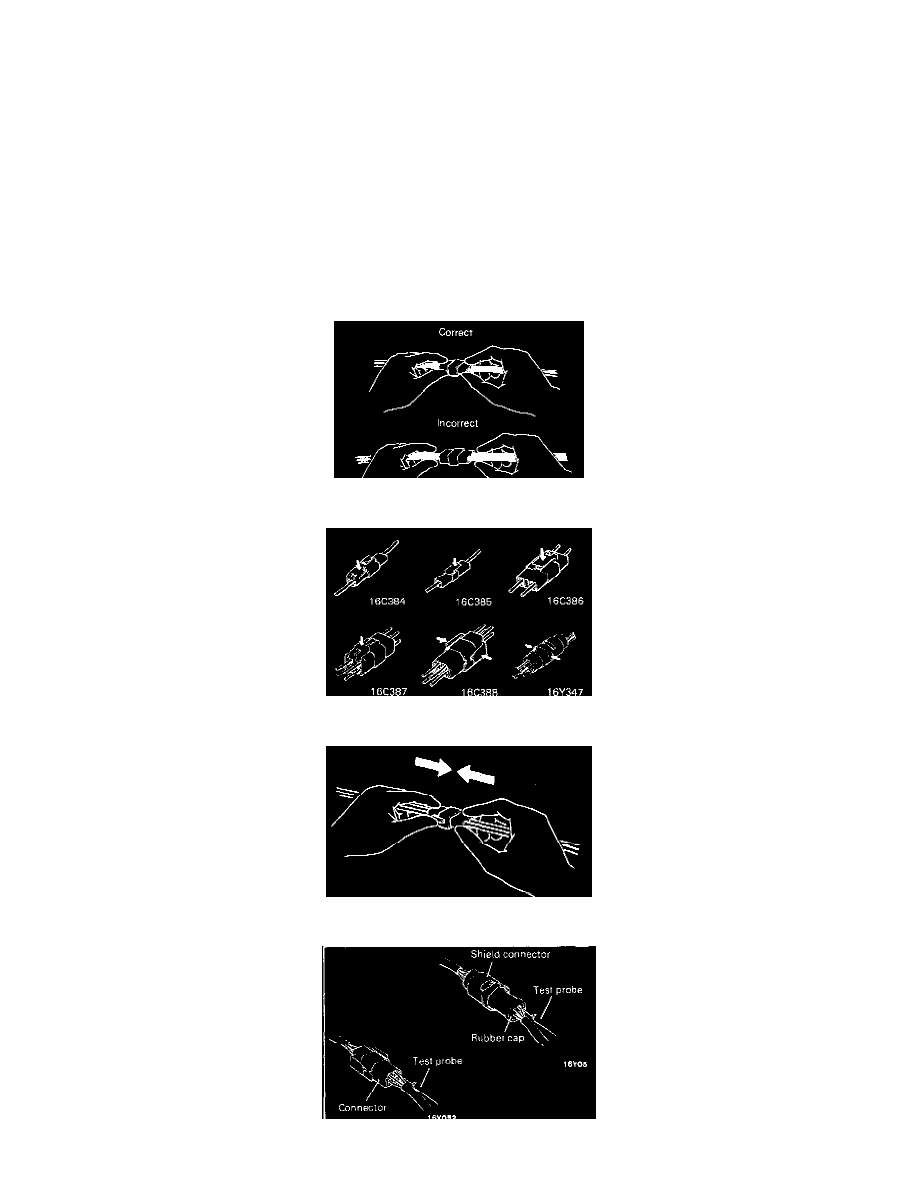
When disconnecting a connector, be sure to pull only the connector, not the harness.
Disconnect connectors which have catches by pressing in the direction indicated by the arrows in the illustration.
Connect connectors which have catches by inserting the connectors until they snap.