
Conquest L4-2555cc 2.6L SOHC Turbo (1984)
3.
Apply a thin coat of clean engine oil to the inside surface of the O-ring before it is installed to the cartridge assembly (Figure 5).
CAUTION:
WHEN THE O-RING IS INSTALLED USE CARE NOT TO DAMAGE IT. A DAMAGED O-RING WILL LEAD
TO OIL LEAKAGE.
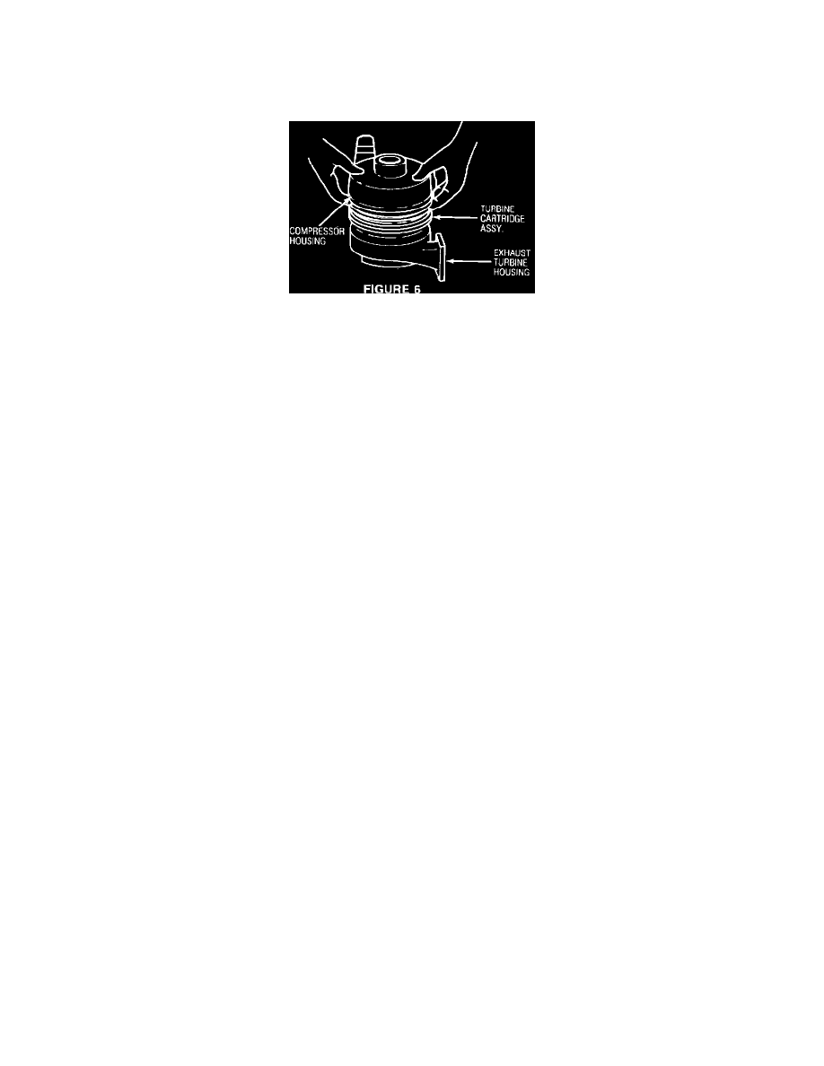
FIGURE 6
4.
Apply a thin coat of clean engine oil to the outer surface of the O-ring installed on the cartridge assembly. Install the compressor cover using firm
pressure to seat it over the O-ring (Figure 6).
5.
With the compressor cover inverted, install the snap ring.
6.
Before installing the turbocharger on the engine, approximately position the locations of the exhaust turbine housing, turbine cartridge assembly
(to locate the oil return pipe), and the compressor outlet for easy installation on the engine.
7.
Install the waste gate actuator assembly to the compressor, but do not fully tighten the mounting bolts. Install the manifold pressure hose between
the compressor housing and waste gate actuator diaphragm.
8.
Install the loosely assembled turbocharger assembly on the engine. Adjust the location of the exhaust turbine housing, turbine cartridge assembly,
and compressor cover for proper alignment of catalytic converter, oil supply and return line, and other related parts.
9.
Before installing the oil supply pipe be sure the oil return hose is permanently installed to turbine cartridge assembly. Next, pour 1/2 pint of clean
engine oil in the oil supply pipe fitting to lubricate the turbine shaft bearings, thus preventing a dry start-up bearing failure. Permanently install the
oil supply pipe.
10.
Tighten the waste gate actuator bolts and torque the coupling band nut to 86.7 inch pounds to 95.6 inch pounds.
11.
Start engine and allow to fully warm up at idle. Check for oil, air, and exhaust leaks. Repair as necessary.
POLICY:
Reimbursable within the provisions of the warranty
TIME ALLOWANCE:
Labor Operation No.
09-44-05-01 - Wastegate Actuator-Replace
0.2 Hrs.
09-44-25-01 - Coupling Band-Replace
0.2 Hrs.
09-44-30-01 - Manifold Pressure Hose-Replace
0.2 Hrs.
09-45-20-01 - Turbocharger-Remove & Install
0.9 Hrs.
09-45-20-50 - Turbocharger-Replace
0.1 Hrs.
09-45-25-50 - Compressor Cover-Replace
0.3 Hrs.
09-45-30-50 - O-Rings-Replace
0.3 Hrs.
09-45-35-50 - Turbine Cartridge Assembly-Replace
0.4 Hrs.
09-45-40-50 - Snap Rings - Replace
0.3 Hrs.
09-45-45-50 - Exhaust Turbine Housing-Replace
0.2 Hrs.
FAILURE CODE:
2X - Vibration or Chatter
07 - Binds, Sticks or Seized
11 - Broken or Cracked
54 - Improperly Assembled
68 - Noisy