
Gran Fury V8-318 5.2L VIN M 4-bbl (1982)
Brake Fluid Pressure Sensor/Switch: Description and Operation
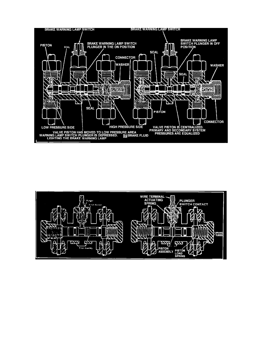
Brake Warning Light Switches
Fig. 4 Pressure differential valve and brake warning light switch
There are four basic types of brake warning light switches as shown, and usually they form a common electrical circuit with the brake warning light.
When a pressure differential occurs between the front and rear brake systems, the valves will shuttle toward the side with the low pressure.
Movement of the differential valve forces the switch plunger upward over the tapered shoulder of the valve to close the switch contacts and light the dual
brake warning lamp, signaling a brake system failure.
Fig. 5 Pressure differential valve and brake warning light switch
The valve assembly consists of two valves in a common bore that are spring loaded toward the centered position. The spring-loaded switch contact
plunger rests on top of the valves in the centered position (right view). When a pressure differential occurs between the front and rear brake systems, the
valves will shuttle toward the side with the low pressure. The spring-loaded switch plunger is "triggered" and the ground circuit for the warning light is
completed, lighting the lamp (left view).