
Grand Voyager V6-201 3.3L VIN R SMFI (1997)
Electronic Brake Control Module: Service and Repair
Removal
PROCEDURE
1. Disconnect the negative (ground) cable from the battery and isolate cable.
2. Using a brake pedal depressor, move and lock the brake pedal to a position past the first inch of pedal travel. This will prevent brake fluid from
draining out of the master cylinder when the brake tubes are removed from the Hydraulic Control Unit (HCU).
3. Raise vehicle. Vehicle is to be raised and supported on jackstands or on a frame contact type hoist.
CAUTION: Do not apply a 12 volt power source to any terminals of the 25 way HCU connector when disconnected.
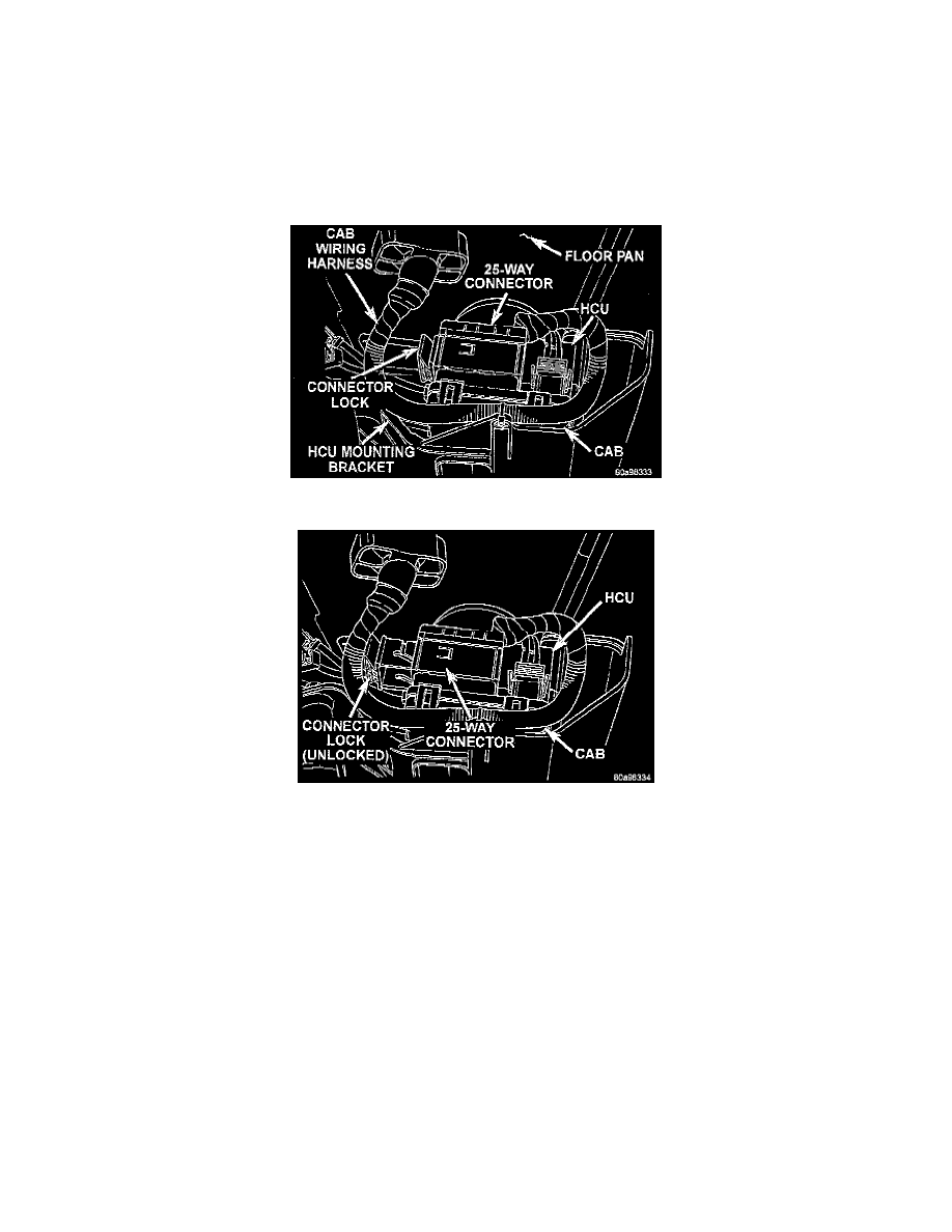
CAB 25 Way Connector
Unlocking CAB 25 Way Connector
4. Remove the 25 way connector from the Controller Antilock Brake (CAB) located on the bottom of the HCU. The 25 way connector is removed
from the CAB using the following procedure. Grasp the lock on the 25 way connector and pull it as far out as possible. This will unlock and raise
the 25 way connector from the socket on the CAB.
CAUTION: Before removing the brake tubes from the HCU, the HCU must be thoroughly cleaned. This must be done to prevent dirt particles
from falling into the ports of HCU or entering the brake tubes.
5. Thoroughly clean all surfaces of the HCU, and all brake tube nuts located on the HCU. Use only a solvent such as Mopar Brake Parts Cleaner or
an equivalent to clean the HCU.