
Grand Voyager V6-201 3.3L VIN R SMFI (1997)
Daytime Running Lamp Control Unit: Description and Operation
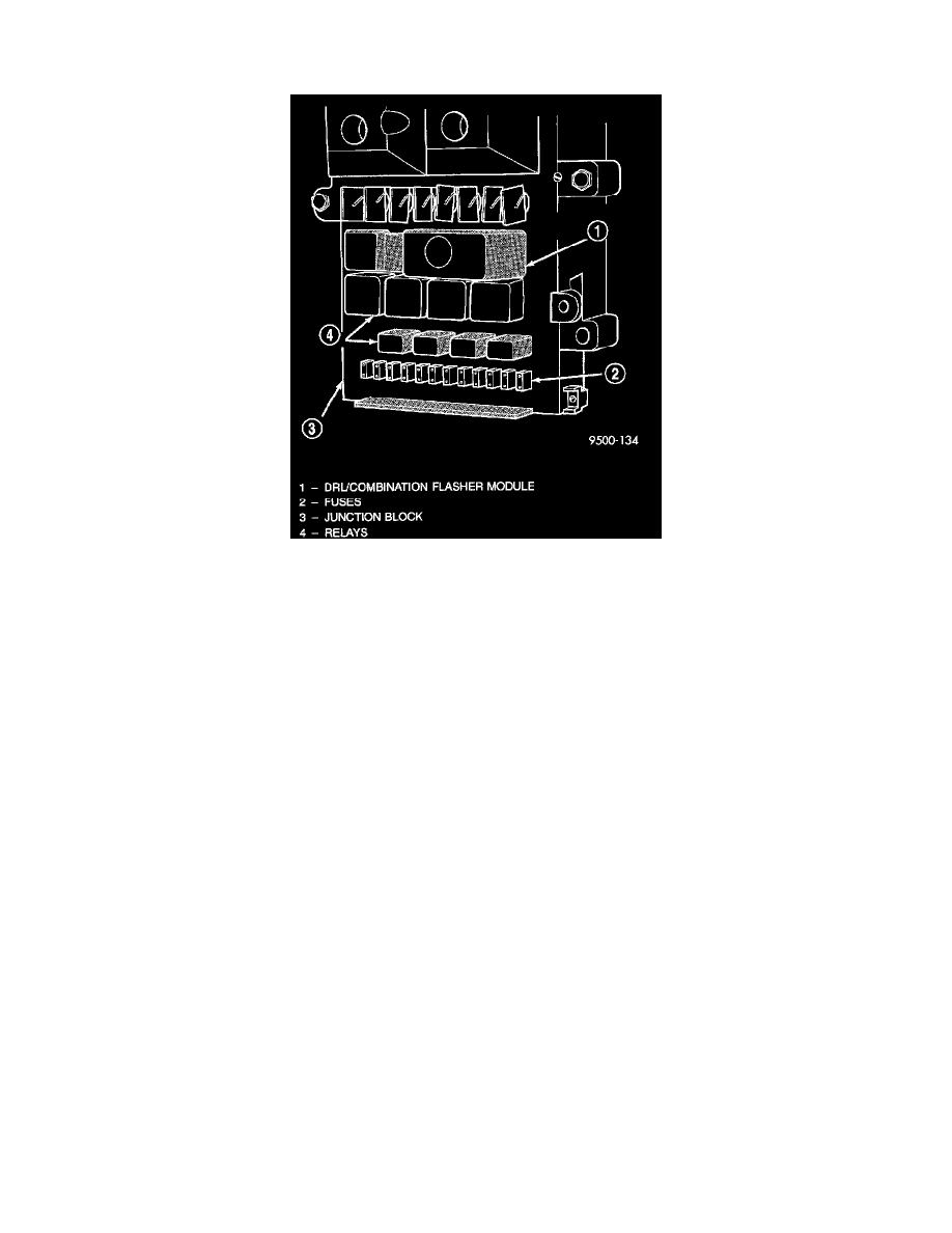
Combination Flasher -- With Daytime Running Lamps (DRL)
Combination Flasher Location
SYSTEM OPERATION
The turn signals are actuated with a lever on the left side of the steering column just ahead of the steering wheel. The signals are automatically
turned off by a canceling cam (two lobes molded to the clock- spring mechanism). The cam comes in contact with the cancel actuator on the turn
signal (multi-function) switch assembly. Either cam lobe, pushing on the cancel actuator, returns the switch to the OFF position.
Lane change signaling is actuated by applying partial turn signal stalk movement toward the direction desired until the indicator lamps flashes in
the instrument cluster. When the switch stalk is released the stalk will spring back into the neutral position turning OFF the turn signal.
With the ignition switch ON and the turn signal switch stalk actuated left or right, current flows through the:
-
Combination flasher
-
Multi-function switch
-
Turn indicator lamp
-
Front and rear turn signal bulbs.
A chime will sound after the vehicle has traveled a distance of approximately 0.5 Mile with the turn signal ON.
FLASHER MODULE DESCRIPTION
The Turn Signal/Hazard Warning Flasher is a module providing the vehicle with turn signal and hazard warning functions and has been designed
with internal relays to take advantage of low current switching requirements in the vehicle. It is plugged into the Junction Block at position 4,
where all wiring associated with its operation is terminated.
The Junction Block is adjacent to and left of the steering column of the vehicle.
To gain access to the flasher, remove the lower steering column cover and knee blocker.