
Grand Voyager V6-201 3.3L VIN R SMFI (1997)
Starter Relay: Testing and Inspection
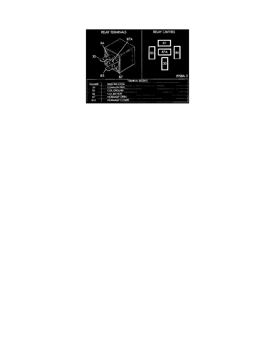
Relay Circuit Test
Starter Relay
1. The relay common feed terminal cavity (30) is connected to battery Voltage and should be hot at all times. If OK, go to Step 2. If not OK, repair
the open circuit to the PDC fuse as required.
2. The relay normally closed terminal (87A) is connected to terminal 30 in the de-energized position, but is not used for this application. Go to Step
3.
3. The relay normally open terminal (87) is connected to the common feed terminal (30) in the energized position. This terminal supplies battery
Voltage to the starter solenoid field coils. There should be continuity between the cavity for relay terminal 87 and the starter solenoid terminal at
all times. If OK, go to Step 4. If not OK, repair the open circuit to the starter solenoid as required.
4. The coil battery terminal (86) is connected to the electromagnet in the relay. It is energized when the ignition switch is held in the Start position.
On vehicles with a manual transmission, the clutch pedal must be fully depressed for this test. Check for battery Voltage at the cavity for relay
terminal 86 with the ignition switch in the Start position, and no Voltage when the ignition switch is released to the On position. If OK, go to Step
5. If not OK with an automatic transmission, check for an open or short circuit to the ignition switch and repair, if required. If the circuit to the
ignition switch is OK, see the Ignition Switch Test. If not OK with a manual transmission, check the circuit between the relay and the clutch pedal
position switch for an open or a short. If the circuit is OK, see the Clutch Pedal Position Switch Test.
5. The coil ground terminal (85) is connected to the electromagnet in the relay. On vehicles with an automatic transmission, it is grounded through
the park/neutral position switch only when the gearshift selector lever is in the Park or Neutral positions. On vehicles with a manual transmission,
it is grounded at all times. Check for continuity to ground at the cavity for relay terminal 85. If not OK with an automatic transmission, check for
an open or short circuit to the park/neutral position switch and repair, if required. If the circuit is OK, see the Park/Neutral Position Switch Test
procedure in this section. If not OK with a manual transmission, repair the circuit to ground as required.