
Laser L4-1997cc 2.0L DOHC (1990)
^
If sub fusible link 4 is fused go to step 3.
2.
Place the light switch in the "HEAD" position and measure the resistance between the switch side of the fuse holder and ground.
^
If there is continuity to ground, locate and repair short in circuit.
^
If circuit is not shorted to ground, replace the fuse and test circuit operation.
3.
Check for continuity between the sub fusible link 4 load end and ground.
^
If there is continuity, locate and repair short to ground, and test circuit operation.
^
If circuit is not shorted to ground go to step 4.
4.
Raise headlamps manually to check for binding or mechanical problems.
^
If a mechanism is binding, repair or replace as needed and test circuit operation.
^
If no binding is encountered, replace the sub fusible link, and test circuit operation.
5.
Remove the cluster panel, set the column switch in the "HEAD" position, and using a voltmeter or test light, test for voltage at the blue/yellow
wire at the back of the pop-up switch connector.
^
If there is voltage go to step 6.
^
If there is no voltage present at the pop-up switch, test for voltage in circuit, working back toward the fuse box. Repair open in circuit and
test circuit operation.
6.
If there is voltage present at terminal 1 (blue/yellow wire) of the pop-up switch, move the probe to the black/blue wire of the passing control relay
connector, and test for voltage.
^
If there is no voltage present, locate and repair the open in the circuit and test circuit operation.
^
If there is voltage present go to step 7.
7.
Test for voltage at terminal 2 (blue/yellow wire) of the passing control relay connector.
^
If no voltage is present at terminal 2 (blue/yellow wire) of the passing control relay connector, replace the passing control relay.
^
If voltage is present at this point go to step 8.
8.
Test for voltage at the pop-up motor connectors (blue/yellow wires).
^
If no voltage is present at this point repair open in wiring and test circuit operation.
^
If voltage is present at this point go to step 9.
9.
Test for voltage at the pop-up motor relay terminals 4 (red/black wire) and 8 (red/blue wire).
^
If voltage is present at this point go to step 10.
^
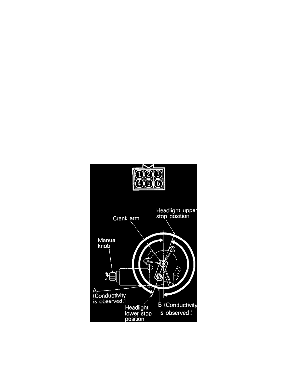
If no voltage is present at this point, perform pop-up motor switch continuity range test below.
Pop-up Motor Switch Adjustment