
Neon L4-2.0L DOHC (1996)
Hydraulic Control Unit: Service and Repair
The content of this article reflects the changes called out by TSB 05-07-94.
REMOVAL
1. Disconnect battery ground cable and isolate cable.
2. Disconnect brake fluid level sensor electrical connector at base of master cylinder.
3. Disconnect primary and secondary brake tubes from master cylinder. Install plugs into master cylinder brake tube outlets.
4. Use a suitable brake cleaner to clean area where master cylinder attaches to power booster.
5. Pump brake pedal until it is firm. This will pump down the vacuum inside the power booster and prevent the booster from sucking in any
contamination when removing the master cylinder.
6. Remove master cylinder to power booster retaining nuts, then slide master cylinder straight out.
7. Disconnect 6-way electrical connector from Hydraulic Control Unit (HCU) wiring harness and 10-way electrical connector from HCU relay box.
8. Remove primary and secondary master cylinder brake tubes from HCU.
9. Remove remaining brake tubes from proportioning valves and HCU outlet ports.
10. Raise and support vehicle.
11. Remove two bolts attaching HCU mounting bracket to side of front of frame rail.
12. Lower vehicle and remove bolts attaching HCU mounting bracket to top of frame rail.
13. Remove HCU and mounting bracket as an assembly from vehicle.
INSTALLATION
1. Install HCU and mounting bracket as an assembly, on left frame rail of vehicle, aligning tabs on mounting bracket with holes in frame rail.
2. Install and loosely tighten bolt attaching HCU mounting bracket to top of frame rail.
3. Raise and support vehicle.
4. Install two bolts attaching HCU mounting bracket to side of front frame rail. Torque bolts to 16 ft. lbs.
5. Lower vehicle and torque bolt attaching HCU mounting bracket to top of frame rail to 9 ft. lbs.
6. Install four chassis brake tubes to HCU proportioning valves and outlet ports, torque brake tube nuts to 12 ft. lbs.
7. Install primary and secondary brake tubes from master cylinder onto HCU, then hand tighten tube nuts.
8. Connect electrical connectors to HCU.
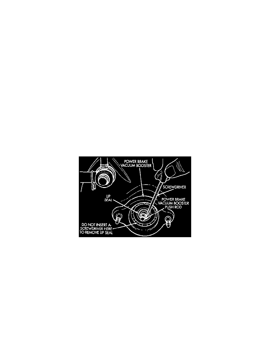
Fig 61 Power Brake Booster Vacuum Seal Removal
9. Using a small screwdriver, carefully remove vacuum seal from front of power brake booster. Do not attempt to pry seal out of master cylinder by
inserting a tool between seal and power brake vacuum booster.
10. Remove old vacuum seal from master cylinder, if seal came out of power brake vacuum booster when master cylinder was removed.