
Neon L4-2.0L SOHC (1995)
EGR Control Solenoid: Description and Operation
Electronic EGR Transducer (EET) Solenoid Operation
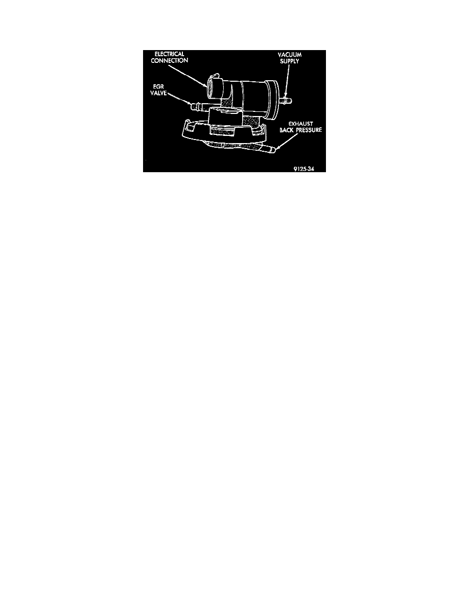
Fig. 2 Electronic EGR Transducer (EET)
ELECTRONIC EGR TRANSDUCER (EET) SOLENOID
Circuit F18 supplies battery voltage to the EET solenoid. The Powertrain Control Module (PCM) switches ground path for the solenoid ON and
OFF through circuit K35.
Circuit F18 connects to a bus bar in the fuse block fed by circuit A21. A 15 amp fuse in the fuse block, cavity 10, protects circuit F18. Circuit F18
connects to cavity 54 of the PCM, and splices to the solenoid connector.
Circuit K35 connects to cavity 39 of the PCM, and cavity 2 of the solenoid connector.