Neon L4-2.0L VIN C (1997)

Cruise Control Switch: Testing and Inspection
The speed control switches mounted on the steering wheel contain five switches and four resistors. The PCM sends 5 Volts through pin 41 to the speed
control switches. The input on pin 41 is responsible for identifying the following: Resume/Accelerate, Set/ Coast, On, Off and Cancel. This is
accomplished by multiplexing. Multiplexing allows the PCM to identify more than one signal from a single wire. To accomplish this, the speed control
switch uses resistors that cause different voltage signals at pin 41.
The 5-Volt signal at pin 41 has no path to ground when no buttons are depressed, allowing the PCM to recognize the open circuit. When the ON, OFF
switch contacts are closed, the 5 Volt signal is pulled through a 15400 ohm resistor to ground providing a voltage of 4.14 to 4.73 Volts at pin 41. Once
the PCM recognizes the ON signal, the PCM provides a battery voltage signal to the speed control servo through pin 5 of the 80-way connector.
When the SET/COAST switch is depressed, a momentary contact closes a path to ground through a 2,940 ohm resistor. This causes a voltage of
approximately 1.99 to 3.20 Volts at pin 41, indicating that the SET/COAST switch has been depressed. When the RES/ACCEL switch is depressed, a
momentary contact closes to ground through a 6,650 ohm resistor. The 5-volt signal then passes through a higher resistance than that of the
SET/COAST switch, causing the voltage to be approximately 3.30 to 4.14 Volts. When the OFF switch is depressed, the contacts close directly to
ground, causing the 5-Volt signal to drop to 0 Volts. When the CANCEL is pressed the contact closes to ground through a 920 ohm resister, causing
voltage at pin 41 of 0.61 to 1.94 Volts.
Ohmmeter Check Of Switch
Speed Control Switch
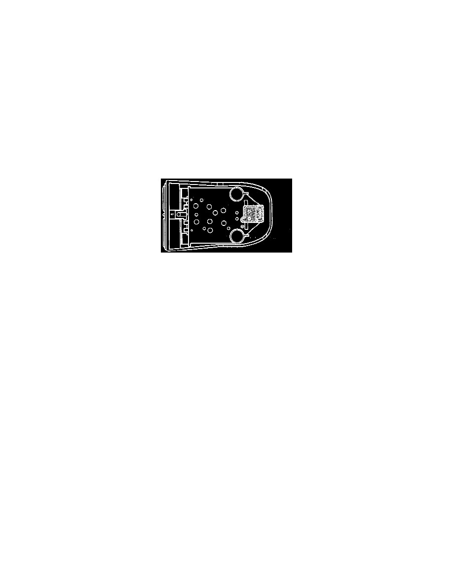
1. Remove the ON, OFF speed control switch assembly and disconnect the two-way connector.
2. Using an ohmmeter, touch one lead to one Pin and the second lead to the other Pin. The meter should read no continuity. Press the OFF button,
the ohmmeter should read 0 to 0.5 ohms. Press the ON button, the ohmmeter should read 15,245 to 15,555 ohms. If the resistance does not
fall within these values replace switch.
3. Remove the RESUME/SET/CANCEL speed control switch assembly and disconnect the two-way connector.
4. Using an ohmmeter, touch one lead to one Pin and the second lead to the other Pin. The meter should read no continuity Press the SET button,
the ohmmeter should read 2,910 to 2,970 ohms. Press the RESUME button, the ohmmeter should read 6,580 to 6,720 ohms. Press the
CANCEL button, the ohmmeter should read 900 to 920 ohms. If the resistance values do not fall within these specification replace the switch.
