
PB 150 V8-318 5.2L VIN T 2-BBL (1983)
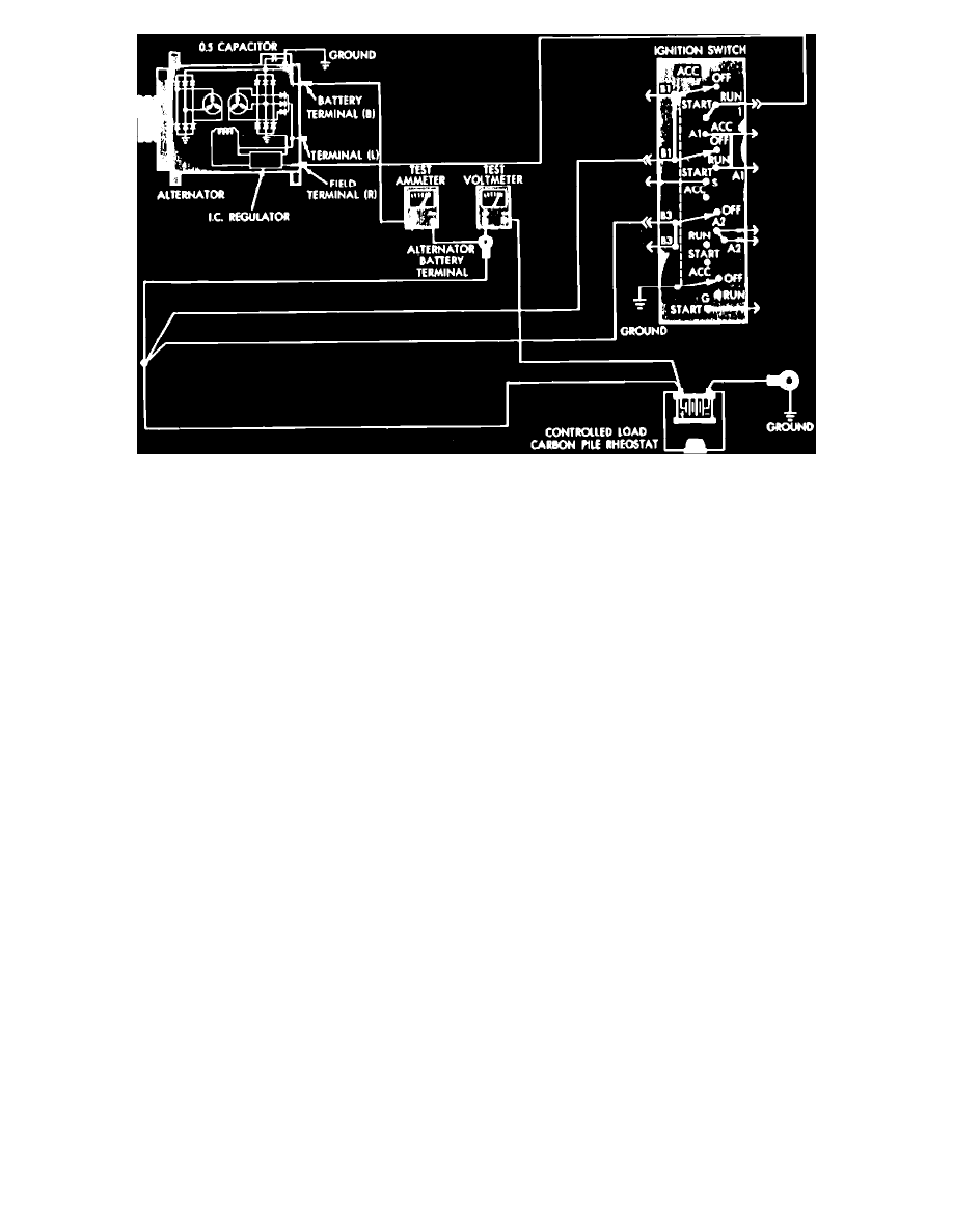
Fig. 6 Charging circuit resistance test connections
1.
Disconnect battery ground cable.
2.
Disconnect "BAT" lead at alternator output terminal.
3.
Connect an ammeter set at 0 to 100 amp scale in series between alternator output terminal and disconnected lead wire. Connect positive lead to "
BAT" terminal and negative lead to disconnected "BAT" lead.
4.
Connect positive lead of a suitable voltmeter to disconnected "BAT" lead wire, then connect negative lead to battery positive post.
5.
Connect a suitable tachometer to engine, then reconnect battery ground cable.
6.
Connect a variable carbon pile regulator between battery terminals. When installing regulator, ensure it is in "open" or "off" position.
7.
Start engine, then adjust engine speed and carbon pile regulator to maintain 20 amp circuit flow. Ensure voltmeter reading does not exceed .5
volts. If a higher voltage drop is indicated, proceed as follows:
a. Tighten all connections to locate possible source of resistance.
b. Inspect and clean each connection.
8.
If test proves satisfactory, disconnect battery ground cable, then remove ammeter, voltmeter and carbon pile.
9.
Connect battery ground cable.
Alternator & Electronic Voltage Regulator Diagnosis