
Prowler V6-3.5L VIN G (1999)
Crankshaft Main Bearing: Service and Repair
Removal and Installation
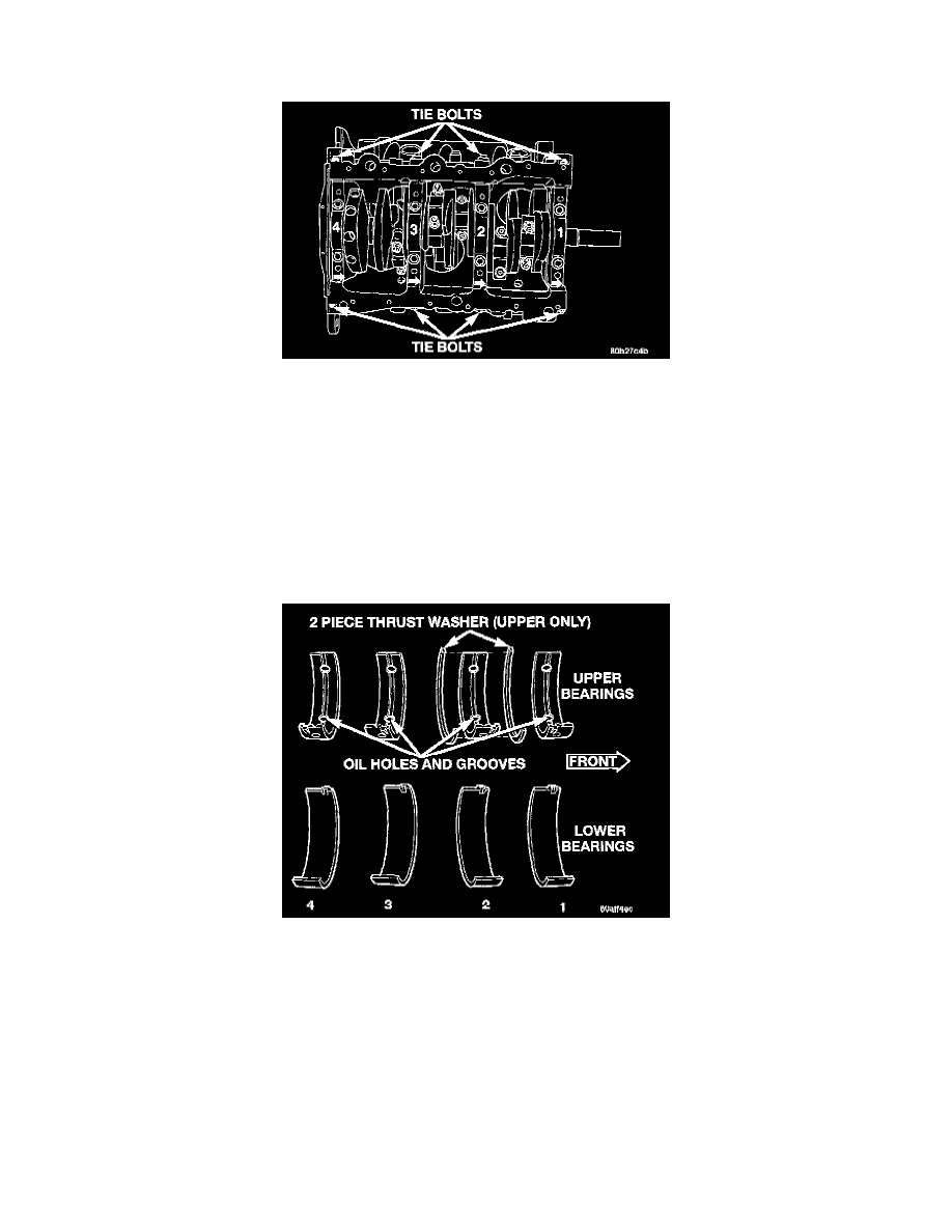
Main Bearing Cap Identification
Bearing caps are not interchangeable and are marked to insure correct assembly. Upper and lower bearing halves are NOT interchangeable.
Crankshaft Main Journals
The crankshaft journals should be checked for excessive wear, taper and scoring. Limits of taper or out-of-round on any crankshaft journals should be
held to 0.025 mm (0.001 inch). Journal grinding should not exceed 0.305 min (0.012 inch) under the standard journal diameter. DO NOT grind thrust
faces of Number 2 main bearing. DO NOT nick crank pin or bearing fillets. After grinding, remove rough edges from crankshaft oil holes and clean
out all passages.
CAUTION: With a forged steel crankshaft it is important that the final paper or cloth polish after any journal regrind be in the same direction as
normal rotation in the engine.
Main Bearing Identification
The crankshaft thrust is controlled with thrust washers located at the upper No. 2 main bearing bulkhead. All bearing cap bolts removed during service
procedures are to be cleaned and oiled before installation. Bearing shells are available in standard and the following undersize: 0.025 mm (0.001
inch) and 0.254 mm (0.010 inch). Never install an undersize bearing that will reduce clearance below specifications.
Removal
1. Remove oil pan, pick-up tube, and windage tray.