
Prowler V6-3.5L VIN G (1999)
Alignment: Service and Repair
Front Alignment
Caster & Camber
GENERAL INFORMATION
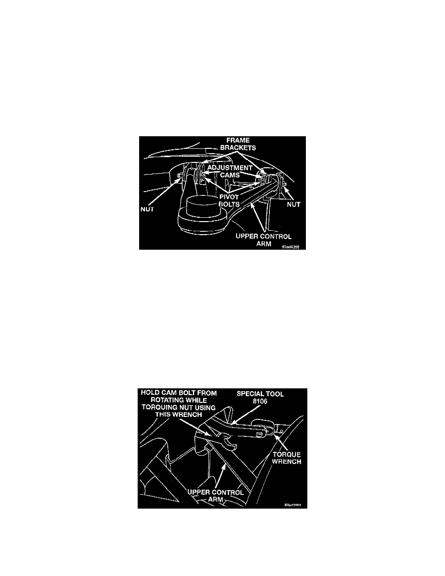
The camber and caster angles on the front suspension of this vehicle are adjustable. The angles are adjusted using adjustment cams. There is one
cam located on each upper control arm pivot bolt. Correct camber and caster specifications are obtained by simultaneously rotating the front and
rear adjustment cams until the upper control arm is correctly positioned.
CAUTION: Prior to any cam bolt rotation, the cam bolt nuts must be loosened. This must be done to allow upper control arm mounting brackets
to be spread allowing free movement of bushings. If not done, serious bending of bracket, weld breakage of cam retainer, fracturing of free cam
and cam bolt shank or thread damage can occur.
CAMBER ANGLE
Camber angle adjustment involves the repositioning of the upper control arm pivot bolts using the adjustment cams. There are two cams one
located on each pivot bolt for the upper control arm. Repositioning of the pivot bolt/cam moves the upper ball joint in or out to obtain the required
camber specifications.
CASTER ANGLE
Caster angle adjustment also involves the repositioning of tile upper control arms pivot bolts using tilt adjustment cams. There are two earls one
located on each pivot bolt for the upper control arm. Repositioning of the pivot bolt/cam moves the upper ball joint in or out to obtain the required
caster specifications.
The front caster angle on this vehicle is read using the caster sweep method and is not read directly off the steering knuckle.
NOTE: When tightening the upper control arm cam bolts using Adapter, Special Tool 8106, the mechanical advantage of a torque wrench is
increased by a factor of 1.5. For this reason the actual torque wrench reading or setting will be lower then the torque specification Example: If the
torque specified is 108 Nm (80 ft. lbs.) the torque wrench reading or setting should be 72 Nm (53 ft. lbs.).