
Prowler V6-3.5L VIN G (1999)
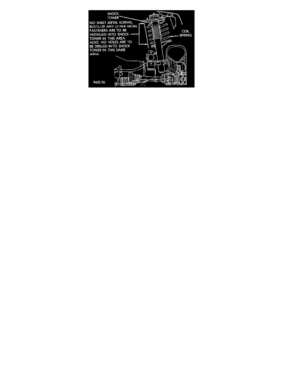
Shock Tower To Spring Minimum Clearance Area
CAUTION: At no time when servicing a vehicle, can a sheet metal screw, bolt, or other metal fastener be installed in the strut tower to take the place of
an original plastic clip. Also, NO holes can be drilled into the front strut tower in the area shown in for the installation of any metal fasteners into the
strut tower.
Because of the minimum clearance in this area , installation of metal fasteners could damage the coil spring coating and lead to a corrosion failure of the
spring. If a plastic clip is missing, or is lost or broken during servicing of a vehicle, replace it only with the equivalent part listed in the parts catalog.
Fuses
CAUTION: When replacing a blown fuse, it is important to replace it with a fuse having the correct amperage rating. The use of a fuse with a rating
other than that indicated may result in an electrical overload. If a properly rated fuse continues to blow, it indicates a problem that should be corrected.
Notes, Cautions and Warnings
Additional important information is presented in three ways: Notes, Cautions, and Warnings.
NOTES are used to help describe how switches or components operate to complete a particular circuit. They are also used to indicate different
conditions that may appear on the vehicle. For example, an up-to and after condition.
CAUTIONS are used to indicate information that could prevent making an error that may damage the vehicle.
WARNINGS provide information to prevent personal injury and vehicle damage. Below is a list of general warnings that should be followed any time a
vehicle is being serviced.
WARNING:
-
ALWAYS WEAR SAFETY GLASSES FOR EYE PROTECTION.
-
USE SAFETY STANDS ANYTIME A PROCEDURE REQUIRES BEING UNDER A VEHICLE.
-
BE SURE THAT THE IGNITION SWITCH ALWAYS IS IN THE OFF POSITION, UNLESS THE PROCEDURE REQUIRES IT TO
BE ON.
-
SET THE PARKING BRAKE WHEN WORKING ON ANY VEHICLE. AN AUTOMATIC TRANSMISSION SHOULD BE IN PARK.
A MANUAL TRANSMISSION SHOULD BE IN NEUTRAL.
-
OPERATE THE ENGINE ONLY IN A WELL-VENTILATED AREA.
-
KEEP AWAY FROM MOVING PARTS WHEN THE ENGINE IS RUNNING, ESPECIALLY THE FAN AND BELTS.
-
TO PREVENT SERIOUS BURNS, AVOID CONTACT WITH HOT PARTS SUCH AS THE RADIATOR, EXHAUST MANIFOLD(S),
TAIL PIPE, CATALYTIC CONVERTER, AND MUFFLER.
-
DO NOT ALLOW FLAME OR SPARKS NEAR THE BATTERY. GASES ARE ALWAYS PRESENT IN AND AROUND THE
BATTERY.
-
ALWAYS REMOVE RINGS, WATCHES, LOOSE HANGING JEWELRY, AND LOOSE CLOTHING.
Positive Temperature Coefficient
Positive Temperature Coefficient (PTC) devices are being used for circuit protection. These PTC's act like a solid state fuse. They are located in the